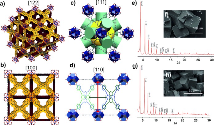
Figure 1.

Structure and phase purity of as-made single linker phases. Single-crystal structure showing a 2×2×2 unit cell of 1 viewed along the [ 2
2 ] direction (a) and [100] direction (b); the three-dimensional porosity of 1 is shown by Connolly surfaces calculated using a 1.2 Å probe radius with the surfaces internal to the framework shown in yellow and the external surfaces shown in brown.[23] c) Cubic cages in 1 with an effective pore diameter of 18.7 Å indicated by the yellow sphere with maximum window diameters for a spherical probe of 7.6 Å indicated by the green cylinders. d) Four-membered windows interconnecting cubic cages along [110], the two crystallographically independent linker conformations are shown in dark blue and dark green with the symmetry equivalent linkers shown in light blue and light green, respectively. Maximal window dimensions based on measured minimum interatomic distances are 17.115(8) Å between the SBUs (direction indicated by the red arrow) and 12.783(4) Å between the linkers in parallel orientations (light blue–dark green), 11.815(4) Å between those in alternating orientations (light blue–dark blue) or 9.272(3) Å between those with a common orientation (light green–dark blue) (direction indicated by the dark green arrow). e) PXRD pattern of as-made 1. f) SEM micrograph of as-made 1. g) PXRD pattern of as-made 2. h) SEM micrograph of as-made 2.
