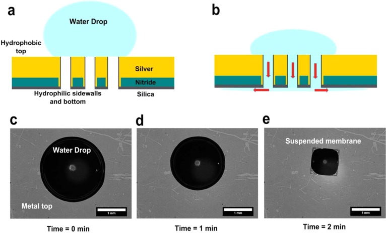
Figure 4.
Schematic for surface-tension-induced flow through nanoholes. (a) Aqueous solution is placed over the nanoholes. The top metal surface is hydrophobic, whereas the silica layer within the holes and on the backside of the chip is hydrophilic. (b) Hydrophilic nanohole sidewalls suck in the solution, driving the flow toward the back of the chip (shown as red arrows). (c–e) Bright-field images showing flow of a 2 μL drop of water through the suspended nanohole array within 2 min. The water drop shrinks as it is sucked in through the hydrophilic nanohole sidewalls.

