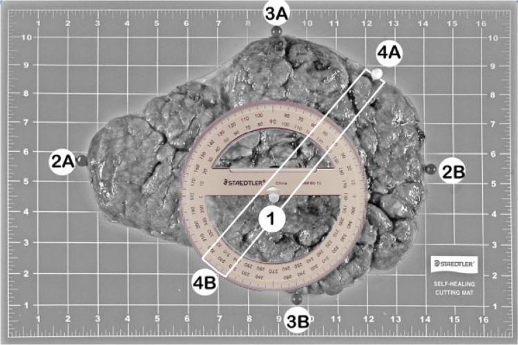
Figure 4.
This image illustrates the coordinates to be used for the sampling of the placental disc; the same image was repeated after coordinate markers and protractor were added to the placental disc. Frequently, these two images were combined. The maternal surface of the placenta shows the landmarks and placement of the protractor. The placenta is oriented with the long axis horizontal. Locations of the landmarks are marked with pushpins: (1) location of the umbilical cord insertion point (on the fetal side of the placenta); (2A and 2B) leftmost and rightmost borders; (3A and 3B) topmost and bottommost borders. For multiple gestations, additional landmarks were recorded regarding the position of dividing membranes. Coordinates for these landmarks were recorded in the data collection forms. The pins labeled 4A and 4B show the borders marking the randomly assigned sampling axis. The protractor is centered at the landmark corresponding to the location of the umbilical cord insertion point. The white lines indicate the central 2-cm strip, which is used for the histological samples.

