FIGURE 7.
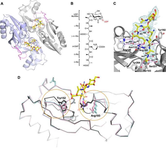
A, the crystal structure of the AmpR EBD dimer (monomers indicated by purple and gray schematics) bound to UDP-MurNAc-pentapeptide (stick format; oxygen atoms are indicated in red, nitrogen atoms in blue, and carbon atoms in yellow) refined to 2.15 Å resolution. The hinge regions connecting each subunit within a monomer are colored magenta. The UDP moiety of the repressor was disordered and not visible in electron density maps, as were some of the MurNAc sugars. B, chemical schematic of UDP-MurNAc-pentapeptide (the UDP moiety not visible in the electron density maps is colored red). C, σ-A-weighted 2Fo − Fc density map contoured at 1.0σ showing the MurNAc-pentapeptide portion of the repressor bound within the AmpR effector-binding pocket. Hydrogen-bonding interactions between residues forming the binding site and the pentapeptide stem of the repressor are shown by dashed magenta lines. Waters are shown as red spheres. D, superposition of AmpR EBD monomers comprising the asymmetric unit of the AmpR EBD·UDP-MurNAc-pentapeptide crystal structure (gray) with the AmpR EBD bound to MES (PDB entry 3KOS; shown in cyan) and the inactivated variant AmpR EBD (T103V/S221A/Y264F) (PDB entry 3KOT; shown in pink). UDP-MurNAc-pentapeptide and MES molecules are represented by sticks, with carbon atoms indicated in yellow and pink, respectively, and oxygen and nitrogen atoms in red and blue. Regions with relative shifts in loop/residue position are circled in orange.

