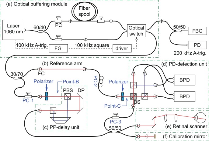
Fig. 1.
Schematic diagram of the optically buffered JM-OCT system. An (a) optical buffering module makes a 200 kHz laser sweep. The JM-OCT system is composed of a (b) reference arm, (c) passive polarization delay unit (PP-delay unit), (d) polarization diversity detection unit (PD-detection unit), (e) retinal scanner, and (f) calibration mirror. PC: polarization controller, FG: function generator, FBG: fiber Bragg grating, PD: photo-detector, FC: fiber collimator, PBS: polarizing beam-splitter, DP: dove prism, BS: non-polarizing beam splitter, BPD: balanced photo-detector. Point-B and -C indicate particular points which are discussed in Section 6.3 and PC-1 and -2 correspond to those in Fig. 6.

