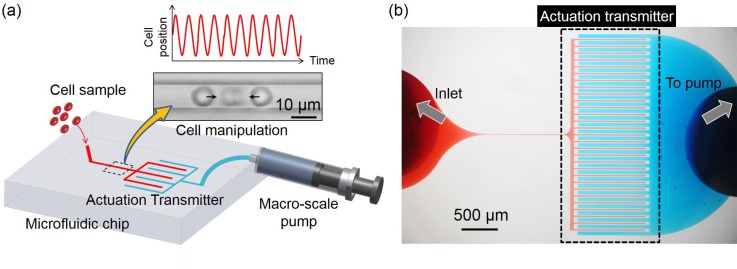
FIG. 1.
The overview of the proposed actuation transmitter. (a) Samples are injected into the chip from the left inlet into the manipulation circuit (red) and manipulated by the separated control circuit (blue) through the actuation transmitter. (b) A photograph of the actual microfluidic system where the two circuits are filled with different color dyes for identification.

