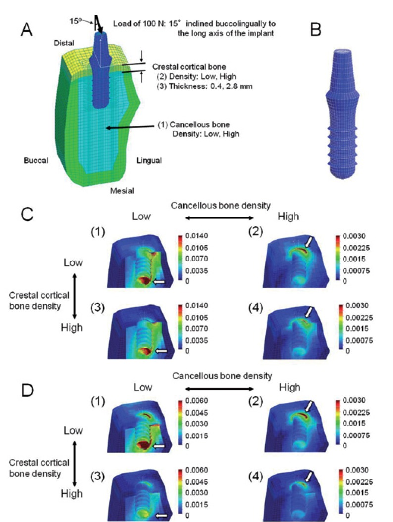
Figure 2.
A, B) Finite-element model. A) Cross-sectional view of the symmetry plane. The three independent parameters include: (1) density of cancellous bone, (2) density of crestal cortical bone, (3) thickness of crestal cortical bone. B) Implant and abutment. C) Equivalent strain distribution in models with thin (0.4 mm) crestal cortical-bone. The implant is removed in this illustration. (1) Model with low-density cancellous and crestal cortical-bone, (2) model with high-density cancellous-bone and low-density crestal cortical-bone, (3) model with low-density cancellous bone and high-density crestal cortical-bone, (4) model with high-density cancellous and crestal cortical-bone. The arrows indicate sites where the peak EQV strains were generated. D) Equivalent strain distribution in models with thick (2.8 mm) crestal cortical bone. The implant is removed in this illustration. (1) Model with low-density cancellous and crestal cortical-bone, (2) model with high-density cancellous bone and low-density crestal cortical-bone, (3) model with low-density cancellous bone and high-density crestal cortical-bone, (4) model with high-density cancellous and crestal cortical-bone.

