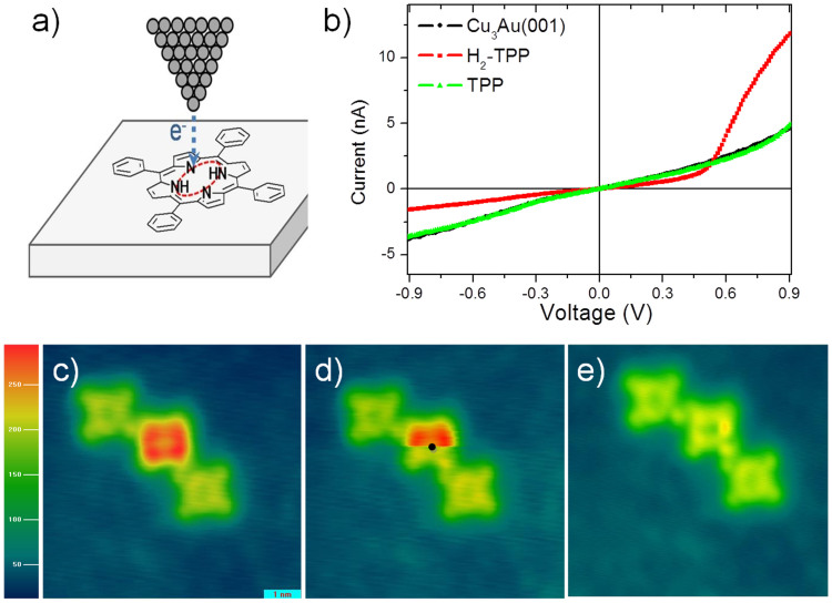
Figure 4. STM tip-induced dehydrogenation of a single H2-TPP molecule.
(a) Schematic illustration showing the dehydrogenation induced by the STM current. In this case, when applying 2.1 V with the STM tip on the center of the H2-TPP molecule the two hydrogen atoms are dissociated. (b) Typical I–V curves measured at the center of the H2-TPP molecule before and after the dehydrogenation. The I–V curve of the Cu3Au substrate is shown for comparison. (c–e) Sequence of STM images of the dehydrogenation process of the H2-TPP molecules on Cu3Au. (c) Three molecules, 2 TPP and 1 H2-TPP in the center. (d) The black dot illustrates the position when voltage is applied and the Hs were dissociated. (e) STM image after the dehydrogenation. STM topographic image were obtained at 0.54 V and 2.0 nA.

