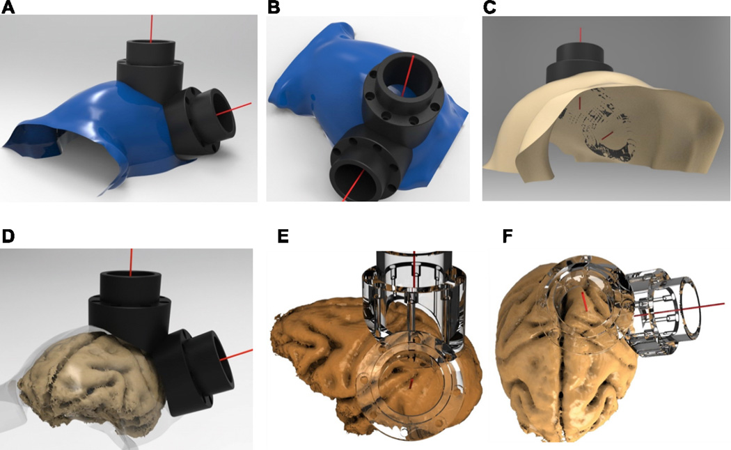
Figure 5. Skull-surface matched head post and dual-chamber system (V4 and LIP).
A–B. Smoothed segmented skull (blue) created using the Analyze software and rendered in PowerShape software, along with V4 and LIP implants. The red line stemming from the center point of each chamber depicts the target vector, which was also generated in Analyze. C. Bottom-view of skull, demonstrating the contoured fit of the base of the chambers to the skull. D. Smoothed skull surface rendered transparent to illustrate relative locations of brain and skull surfaces to superimposed chambers. E–F. Co-registered brain and transparent chambers illustrate accurate targeting of brain structures. Lower-right quadrant visual field representation is targeted in area V4 (E), with the center of the chamber aimed between the lunate and superior temporal sulcus. Intraparietal sulcus and area 5 are targeted in a chamber placed over the posterior parietal cortex, used for a dorsal approach to area LIP (F).

