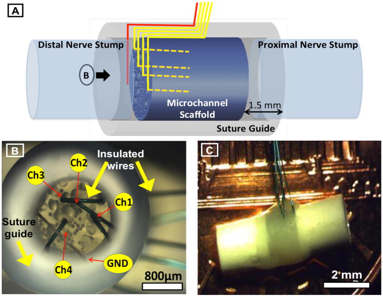
Figure 2.

Details of microchannel neural interface. A. Schematic representation of the peripheral neural interface with customizable PDMS microchannels and integrated microwire electrodes, illustrating the 3mm long PDMS microchannel scaffold (blue), the surrounding polysulfon suture guide (gray), the integrated microwire electrodes transiting between the suture guide and scaffold to the distal end and then entering microchannels (yellow), and the ground wire at the distal end of the device (red). Proximal and distal nerve stumps are shown to illustrate configuration after implantation. B. Microscope photograph view of the distal end of the neural interface prior to implantation (shown by the arrow marked B in panel A). Microchannels of 200 and 75 μm diameters are visible on the distal face of the PDMS scaffold. Microchannels containing microwire electrodes (200μm) are labeled (Ch1-4) as well as the ground wire (GND). Insulated microwires are seen transiting between the microchannel scaffold and the suture guide prior to exiting the device. C. Microscope photograph of the final assembled neural interface prior to implantation illustrating the external polysulfon suture guide and exiting microwires.
