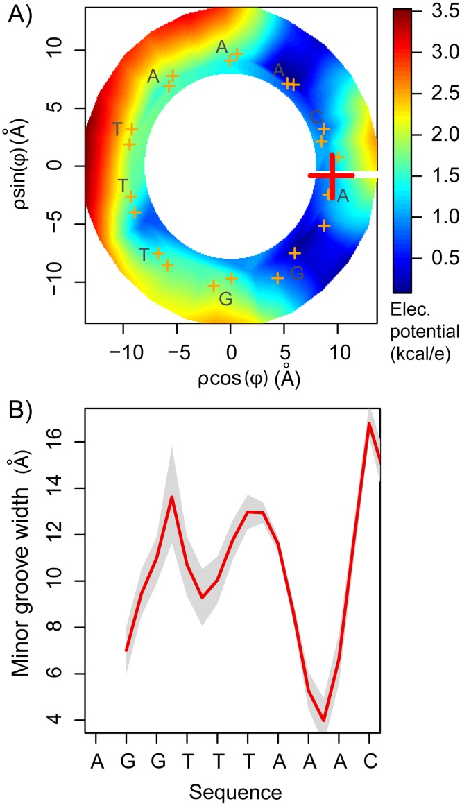
Figure 6. The minor groove environment.
A) Electrostatic potential inside the minor groove. The potential has been rescaled such that the minima in the studied region was set to 0 to facilitate the comparison with the computed PMF. B) The minor groove width was computed using the software Curves [51]. Grey shadows correspond to one standard deviation. For examples of different structures see S5 Fig..

