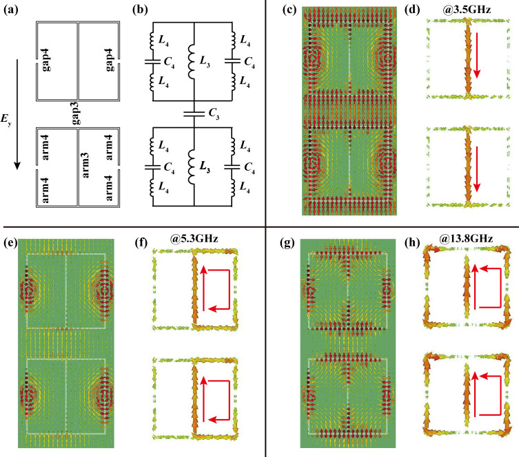
Figure 6. Circuit model of the proposed structure under the y-polarization.
(a) Origination of the inductor and capacitor when the electric field is polarized along the y-direction. (b) Equivalent LC circuit model for the y- polarization. (c) Electric field distributions and (d) volumetric current flows at f3 = 3.5 GHz (zero point of Zy). (e) Electric field distributions and (f) volumetric current flows at f4 = 5.3 GHz (polar point of Zy). (g) Electric field distributions and (h) volumetric current flows at f5 = 13.8 GHz (zero point of Zy).

