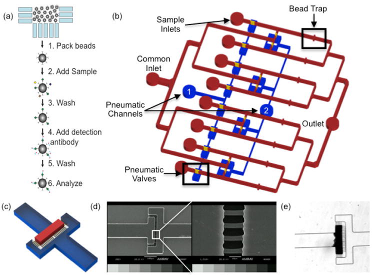
Fig. 1.

a) Microimmunoassay principle. Antibody conjugated microbeads are packed into the bead traps. Sample is then flowed over the bead beds followed by a wash step. Detection antibody is then added, the beads are washed, and the sample is ready for analysis b) Schematic representation of the microimmunoassay device. A common inlet is used for flowing all assay reagents including blocking buffer, wash buffer, antibody coated microbeads, detection antibodies, and fluorophores. Individual sample inlets allow for the simultaneous analysis of eight samples. Downstream of each sample inlet, an array of 3 μm channels acts as a bead trap to create a packed bed that functions as a reaction chamber. A common outlet discards waste from the assay and also is used as an inlet during collection of the microbeads at the completion of the assay. Pneumatic valves are used to direct fluid flow throughout the assay. Whenever the common inlet is in use, pneumatic channel 1 is pressurized so fluid flows from the common inlet through the bead traps. During sample incubation and bead collection, pneumatic channel 2 is pressurized to prevent mixing between adjacent channels. c) 3D schematic of the bead traps. The bead bed is immobilized in the area denoted in red and the bead trap is comprised of the array of yellow features d) SEM image of the bead trap e) Brightfield micrograph of a packed bed of microbeads upstream of the bead trap
