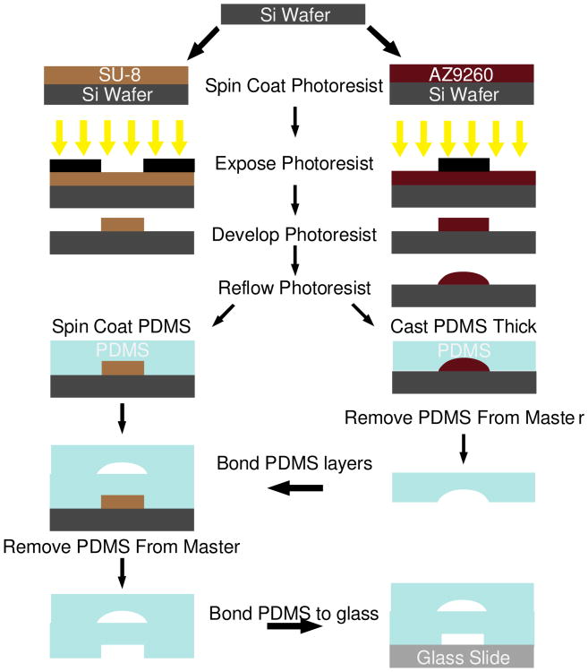
Fig. 3.
Schematic of the device fabrication procedure, with each photolithography step represented by a single color in the device schematic in Fig. 1b. All layers are fabricated using SU-8 with the exception of the valve seats which are made using AZ9260. Photolithography is performed using standard techniques. The AZ9260 layer is reflowed after development to create rounded channel architecture necessary for complete pneumatic valve closure. The fluidic layer and control layers are fabricated on two separate wafers. The fluidic layer is created by casting a thick layer of PDMS, while the control layer is spin-coated with PDMS yielding a thin layer. The thick layer is bonded to the thin layer, and then both layers are bonded to a glass slide

