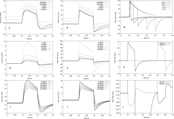
FIG. 9.
Equivalent circuit calculation of droplet generator nozzle pressure and flows: The pressures are all relative to atmospheric pressure at the nozzle inputs, and the flow rates are those over the nozzles. All values of components apart from those explicitly varied are taken from the supplementary material Table S11.35 (a)–(g) One nozzle circuit from Fig. 10. (h) and (i) Two nozzle circuit. Hydrodynamic resistance parameter values are displayed as electrical equivalent with 1 GΩ = 103 MΩ ≈1015 Pa s/m3 = 1 kPa s/nl ≅ 10 mbar s/nl. (a) and (d) Pressure and flow rate profile during injection as a function of tuning resistor. (b) and (e) Pressure and flow rate profile during injection as a function of nozzle resistance (corresponding to nozzle ledge heights 1–2 μm). (c) and (f) Pressure and flow rate profile during injection as a function of microfluidic channel resistance at sample exit (varying from narrower input channel to broader realized exit channel resistance). (g) Droplet flow rate as a function of impulse time. (h) and (i) Independent operation of two nozzles. The influence of one nozzle on the other is only visible in the blowup scale of e′. Flow rates: central channel: 20 μl/h, side channel: 100 μl/h, impulse time is 0.1 s, unless otherwise specified.

