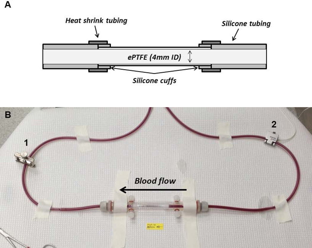
Figure 1. Ex vivo shunt study set up.
Cross-sectional diagram of the graft construction allowing for smooth luminal transitions between the ePTFE and silicon shunt tubing (A). Image of the ex vivo flow loop with the tubular ePTFE construct in a biochamber (B). The clamp, labeled 1, is used to maintain a flow rate at 100 mL/min measured by the flow probe, labeled 2.

