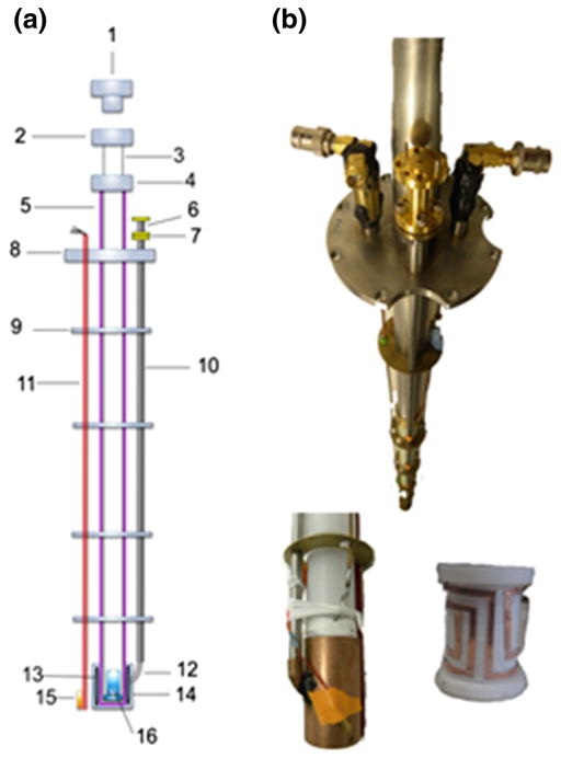
Fig. 3.
DNP probe insert. a Schematic diagram of the DNP probe: (1) brass plug, (2 and 4) coupling pieces, (3) inner sliding tube, (5) outer support tube, (6) rectangular to circular transition waveguide, (7) homebuilt waveguide adapter, (8) stainless steel plate, (9) brass plate heat shields, (10) stainless tube waveguide, (11) liquid helium level sensor, (12) 90° waveguide bend, (13) NMR saddle coil, (14) microwave cavity, (15) temperature sensor and (16) sample cup; b Photographs of the DNP probe showing the two NMR ports and microwave waveguide (top), as well the microwave cavity (bottom left) and the rectangular saddle NMR coil inside the cavity (bottom right)

