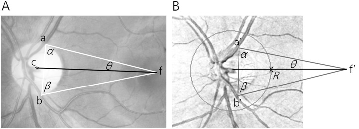
Fig 1. Fundus photograph and retinal nerve fiber layer (RNFL) thickness deviation map showing the new reference lines.
The new reference line (black line) on the fundus photograph (A) connects the geographic center of the optic nerve head (point c) and the fovea (point f). The white triangle has corners at the fovea (point f) and the points where the temporal borders of the superior temporal retinal vein (point a) and the inferior temporal retinal vein (point b) cross the disc margin. Side a-f and the line c-f make the angle θ between them. On the RNFL thickness deviation map (B), a similar triangle (gray triangle) was constructed with 2 corners at the points where the temporal borders of the superior temporal retinal vein (point a’) and the inferior temporal retinal vein (point b’) cross the disc margin and side a*-b*. The other corner of the triangle was point f*. Angle θ was measured and a line was drawn to the optic disc (black line). Finally, point R was marked where the scan circle and the line met.

