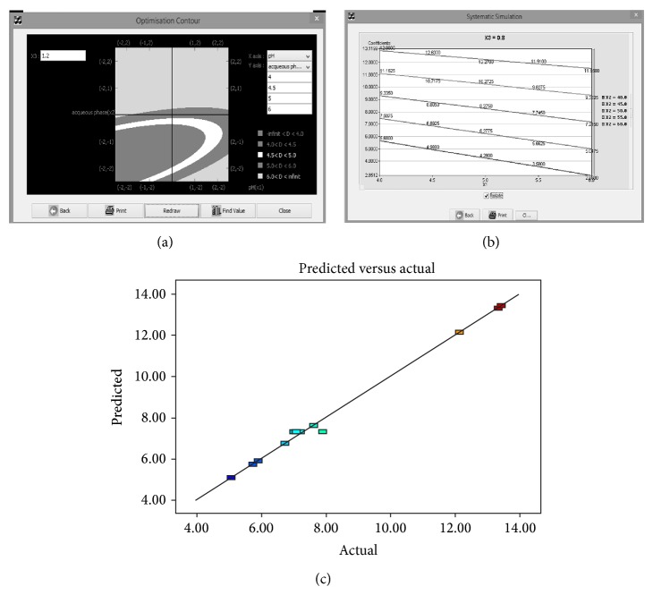
Figure 1.
(a) Contour plot for MODR (retention time as method response). The above graph shows the different shade for different region for retention time at different levels −2, −1, 0, +1, and +2. (b) Systematic simulation graph for retention time (y-axis) as method response at constant X3 (0.8 mL/min as flow rate) with change in pH (X1-x-axis). (c) Graph shows significant correlation between the predicted retention time and actual (experimental) retention time with good correlation coefficient.

