
Figure 4.
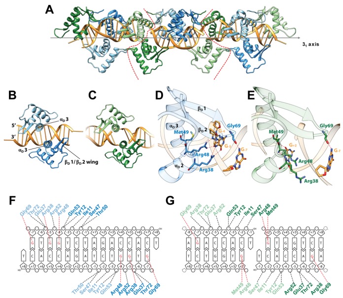
Crystal structure of NagR–DBD in complex with 15mer palindromic dsDNA. (A) The crystallographic asymmetric unit (ASU) comprises four NagR–DBD monomers bound to dsDNA (middle; delineated by red dotted lines). The complex is shown together with two adjacent ASUs that are related by a crystallographic 31 screw axis as indicated. All molecules are shown in a cartoon representation with the centrally-bound NagR–DBD dimer colored in blue and light blue. The edge-bound NagR–DBD dimer is depicted in green and light green. (B) and (C) Close-up view of (B) a centrally-bound NagR–DBD dimer bound to dsDNA forming the dre-site-specific recognition complex and of (C) an edge-bridging NagR–DBD dimer that reveals non-dre-site-specific binding interactions. (D) and (E) Details of the interactions between DNA and (D) a centrally-bound NagR–DBD and (E) an edge-bound NagR–DBD. Only base-directed interactions are shown. Hydrogen bonds are represented by red dotted lines. Interacting residues and bases are shown as stick models. (F) and (G) Schematic summary of the NagR–DBD–DNA contacts formed by (F) the centrally-bound dimer and (G) the edge-bound dimer. Only direct interactions, identified with the analysis software NUCPLOT (30), are shown. Base-specific contacts are indicated in red. Nucleotides in the recognition half-sites are numbered according to their position from the center of the palindrome.