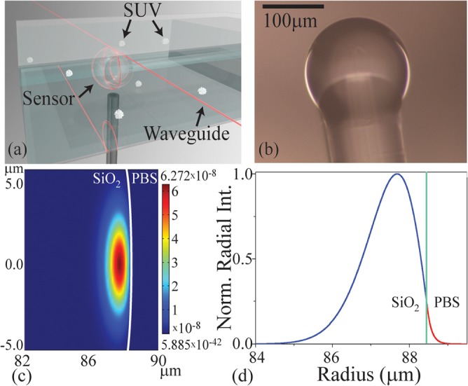
FIG. 1.

Optical resonant cavity excitation. (a) A rendering of the spherical resonant microcavity inside the detection chamber, highlighting the location of the optical field. (b) An optical micrograph of the SiO2 microsphere microcavity before lipid bilayer adhesion. (c) A FEM simulation of the optical mode in the cavity and buffer. (d) The normalized radial intensity distribution at the cross section of the device. The green line indicates the device:buffer interface. A portion of the optical field clearly extends into the buffer and is able to interact with the ∼5–10 nm bilayer.
