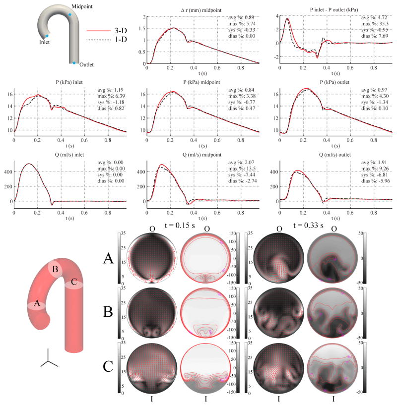
Figure 9.
Single-curvature aorta case. Top: flow rate and pressure with time at the inlet, midpoint and outlet, radius with time at the midpoint, and pressure gradient between inlet and outlet in the 3-D model (solid lines) and 1-D model (dashed lines) with relative error metrics (Section 2.6). Bottom: in-plane (colormap and arrows, left) velocity and out-of-plane (colormap, right) components of the velocity field in the 3-D model at three cross-sections. Velocities are given in cm/s. The outer and inner curvatures are labeled as “O” and “I”, respectively.

