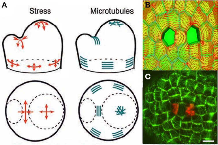
Figure 8.
Mechanosensing of internal loads in the SAM and microtubule re-orientation from Hamant et al. (2008), reprinted with permission from AAAS. (A) Schematic representation of stress directions and microtubule orientations in the different parts of an SAM bearing a cylindrical primordium. (B) Principal stress pattern at the outer surface of the meristem simulated in an FEm of a patch of SAM at the top of the dome with a two-cell ablation. The stress pattern is circumferential to each of the ablated regions and stress alignment is enhanced in the cell between the two ablated cells. (C) Cortical microtubule distribution in the L1 layer in the central zone after a two-cell ablation as visualized by the expression of a construct fusing the Green Fluorescent Protein and the Microtubule Binding Domain (GFP-MBD), Scalebar, 5 μm.

