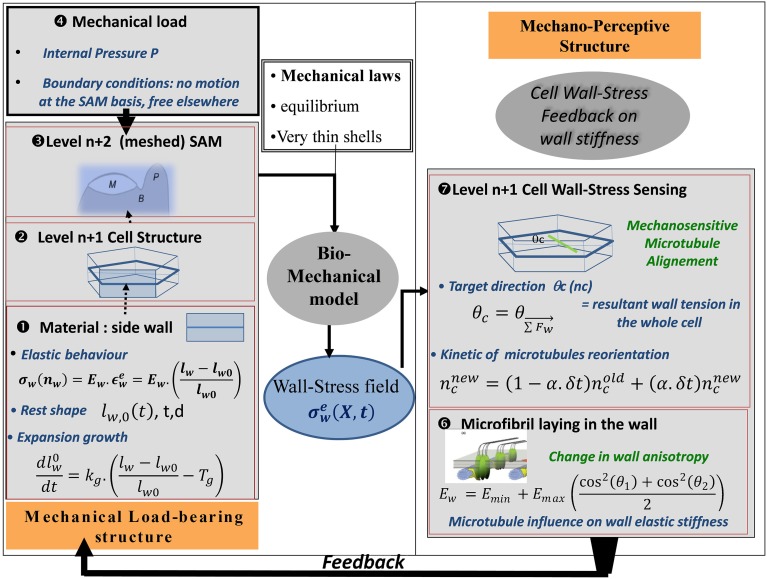
Figure 9.
Schematic representation of the SAM Stress Feedback model (SAM SFm). The SAM SFm (Hamant et al., 2008) incorporates an ISM biomechanical model of the mechanical load-bearing structure of the SAM, and a mechanobiological model of the responses to the mechanical state of a cell in terms of (i) cell-wall stress sensing by CMTs and (ii) the consequences on the longitudinal elastic stiffness of the cell wall due to the direction of the laying down of cellulose microfibrils with respect to the longitudinal direction of the cell wall. The elemental brick of the biomechanical model is a piece of cell wall ❶ (called the cell-wall element) which displays two rheological behaviors: (i) elastic straining and (ii) expansion growth changing the rest length lw,0 of the element at a rate that is proportional to its elastic strain over a certain threshold. Cell wall growth is therefore analogous to visco-plastic creep. The transverse height (d) and thickness (t) of the wall element are assumed to be constant. Two levels of structure can then be assembled. At the first level, ❷ the side walls of a single hexagonal cell are assembled The model can be run at this level, giving rise to the cell-level formulation of the SFm. Otherwise the cells can be assembled to form a surface mesh with typical SAM geometry❸, in the SAM-level formulation of the SFm. The load is the turgor pressure of inner tissues considered to be fully borne by the L1 cell(s) ❹. This ISM biomechanical module outputs the (elastic) wall-stress field σew at every position X on the different cell-wall elements composing the mechanical structure, at a given time, as well as the changes in rest-lengths of all the cell-wall elements due to expansion growth. This updates the geometry of the cellular structure for the next step and the outputs are transmitted to the mechanobiological module. In the mechanobiological module of the SAM SFm, the mechanosensitive step occurs at the level of the cell ❼, as it is an intrinsic cellular process. The central hypothesis of the module is that CMTs are re-aligned to the current direction of the direction of the resulting stress θc, but this occurs at a constant pace with only some of the overall CMT population (ncnew) being reoriented during each step (the rate is assumed to be independent of the mechanical state). The current mean orientations of CMTs in two cells sharing a given cell-wall (θ1(t), θ2(t)) determines the longitudinal elastic stiffness of the side cell wall Ew presumably through the orientation of the laying down of the new cellulose microfibrils with respect to the existing wall, changing the anisotropy of the cell wall elastic rigidity and hence its longitudinal stiffness (here assumed to be instantaneous) ❻ (note that (θ1(t), θ2(t)) may differ from the targeted orientations (θc1, θc2) specified by the stress-feedback as CMT reorientation takes time). The latter process occurs at the level of each cell-wall element so different walls of the same cell differ in the amount of elastic stiffening they undergo. The new value of wall elastic stiffness Ew is the output of the mechanosensitive module and is transferred to the mechanical module, in which the elastic stiffness is updated, immediately changing the constitutive law of the cell walls, and thus giving rise to a new mechanical equilibrium at the next step. This change in wall elastic rigidity is the way the current wall-stress state feeds back on the growth of the meristematic cells. Note that cell division may occur (not shown). A phragmoplast (new cell wall) is laid down parallel to the current CMT direction θ1 whenever the size of the stem passes a certain size threshold thereby changing the structure of the L1 cell wall “mesh.”

