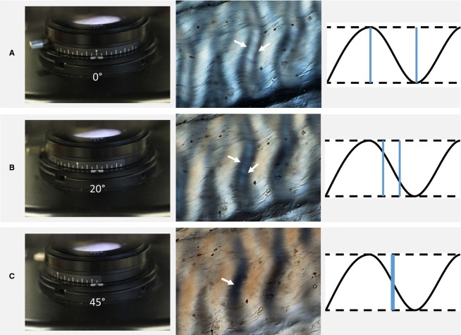
Fig 4.
Crimp angle measurement using polarized light microscopy following the procedure of Diamant et al. (1972). (A) The initial setting of the polarizer at 0˚, orthogonal to the analyser (second polarizer), with the ligament long axis placed along the x–y axis of the stage, results in the DIC image shown here, as well as the crimp wave illustration. The double band (denoted by the two arrows), gradually comes together with the rotation of the polarizer (B). Finally, when the bands merge to form a single dark band (C), the polarizer rotation angle matches the tangent angle of the crimp wave.

