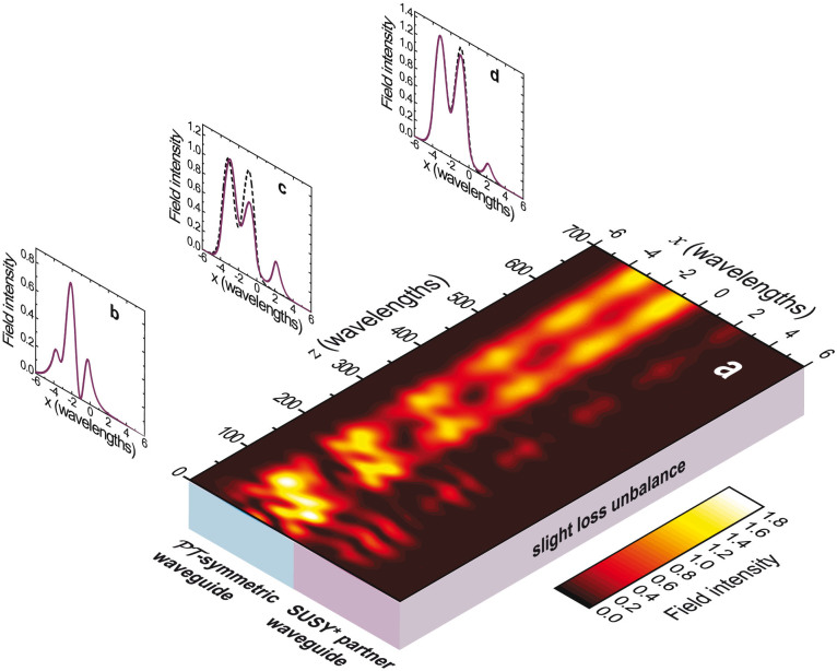
Figure 8. SUSY*-based compound profile in Eq. (19), with w = 2λ0, D = 1.02, |Im(Δε1)| = 0.015, and a slight loss unbalance (ν = 0.0032) in the SUSY*-partner waveguide.
(a) Field-intensity map (in false-color scale) assuming the structure excited by a linear combination of the three guided modes of the original waveguide, with coefficients chosen so that the total power density is equally distributed among the modes. (b), (c), (d) x-cuts (continuous curves) for z = 0 (input profile), z = 335λ0, and z = 700λ0, respectively. As a reference, also shown (dashed curves) in panels (c) and (d) is the normalized intensity profile of the targeted n = 2 mode of the original waveguide.

