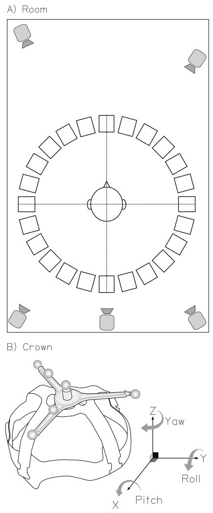
FIG. 1.
Schematic illustration of the experimental apparatus. (A) The acoustically-treated room showing the 360° loudspeaker ring, the 5 infrared motion-tracking cameras, and the listener’s approximate location in the room. (B) The head-mounted crown including reflective markers. This diagram also depicts the 3 Euler angles (yaw, pitch, and roll) and their respective axes of rotation. The directions of the arrows represent positive angles.

