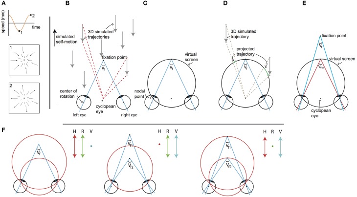
Figure 1.
Visual stimulus explanation and rationale. We equated disparity for all elements in the scene by projection of the 3D cloud on the VM torus, for every element for every frame. The objects on this “virtual projection screen” are in the final stage of each motion frame projected on the real screen in the scanner (not depicted). Seen from the cyclopean eye, 3D motion does not change by the intermediate projection step onto the virtual screen, while that intermediate projection makes horizontal retinal disparity nearly constant for all points. Thus, we decouple the motion field of the cyclopean eye from the binocular disparity. By changing the simulated distances of fixation point and the target vergence of the VM surface independently, one decouples changes of retinal disparity and headcentric disparity. This is illustrated in detail in the following panels. (A) The visual stimulus consists of an optic flow pattern that simulates oscillating (forward/backward) self-motion in depth. The pictograms show the point-motion vectors when the simulated backward (1) and forward (2) speed was maximal. At the zero crossings, simulated self-motion speed was zero and all points were stationary at that instance. (B) Top view of simulated forward motion (black arrow on the left), by presenting approaching dots (gray arrows). For two dots the angular displacement as seen from the cyclopean eye is illustrated (red dashed lines), while the eyes are converged with an angle Vf. Note that the angular velocities and the changing disparities are different for the two points. (C) The top view shows a cross section of the virtual screen, which consists of the Vieth-Muller circle that runs through the fixation point and the eyes' nodal points. The virtual screen is a surface of revolution of the Vieth-Muller circle about the inter-ocular axis. Across the virtual screen the vergence angle of the eyes required to fixate that point (target vergence: TV) is identical. Hence the virtual screen is an iso-vergence surface. (D) To disentangle retinal and headcentric disparity the point motions in (B) are projected on the virtual screen. The projected trajectories as seen from the cyclopean eye are identical to those illustrated by the red dashed lines in (B), showing that the flow as seen from the cyclopean eye remains. However, because the dots are now moving across the virtual screen their TV is constant, which holds for all points on the surface. For the illustrated cross section of the virtual screen, the points' retinal disparities are zero throughout the trajectory. This is not exactly true for points below and above, but the deviations from zero are small for elevations of less than ±25°. (E) When the fixation point moves in depth dissociating the vergence angle of the eyes (Vf) and the target vergence of the virtual screen (VVM) the retinal horizontal disparities of the points that are projected on the virtual surface increase by the difference of those vergence angles (with small deviations depending on the elevation). (F) Our paradigm (to a good approximation) dissociates horizontal retinal disparity and headcentric disparity. The left panel illustrates co-variation of retinal (green arrow) and headcentric disparity (red arrow) while vergence is fixed (blue dot). This happens, when the virtual screen grows to recede in the distance and shrinks on approach. The middle panel illustrates how retinal disparity and eye vergence (blue arrow) co-vary while headcentric disparity remains constant (red dot). This happens, when the eyes converge and diverge in pursuit of the fixation point's motion in depth, while the virtual screen is fixed. The right panel illustrates how headcentric disparity and eye vergence co-vary while retinal disparity is virtually constant (green dot), as occurs when the fixation point remains located in the virtual screen while it grows and shrinks.

