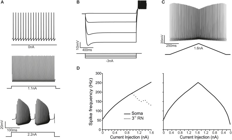
Figure 2.
Electroresponsive properties of the PC model. (A) The traces show spikes in the soma during spontaneous firing and in response to moderate (1.1 nA) and high (2.2 nA) step-current injections in the soma, demonstrating the transition from simple spikes to complex bursting. (B) A series of negative step-current injections in the soma determines voltage responses showing the typical sag and rebound depolarization generated by the H-current. (C) A ramp-current injection (from 0 to 1.6 nA and back) causes a frequency-modulated response in the PC model. (D) In response to step-current injection from 0 to 1.6 nA (0.1 nA steps), the PC model generates proportionately higher spike frequencies. Conversely, the RNs are unable to sustain firing frequencies above 200 Hz (dotted line). In response to ramp-current injection increasing from 0 to 1.6 nA, the f-I curve closely resembles that obtained using step-currents. However, on the way back, the f-I curve is asymmetrical.

