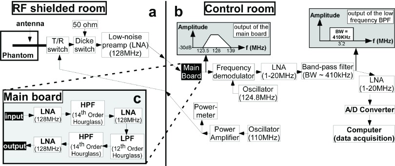
FIG. 3.
Block diagram of the radiometry receiver components. (a) The phantom with the loopless antenna, switches, and first preamplifier stage are placed inside the RF-shielded room. (b) The rest of the RF receiver and power delivery components are located outside the shielded room. (c) RF components in the main board include three preamplifier stages and an anti-aliasing band-pass filter consisting of a low-pass and two high-pass filters.

