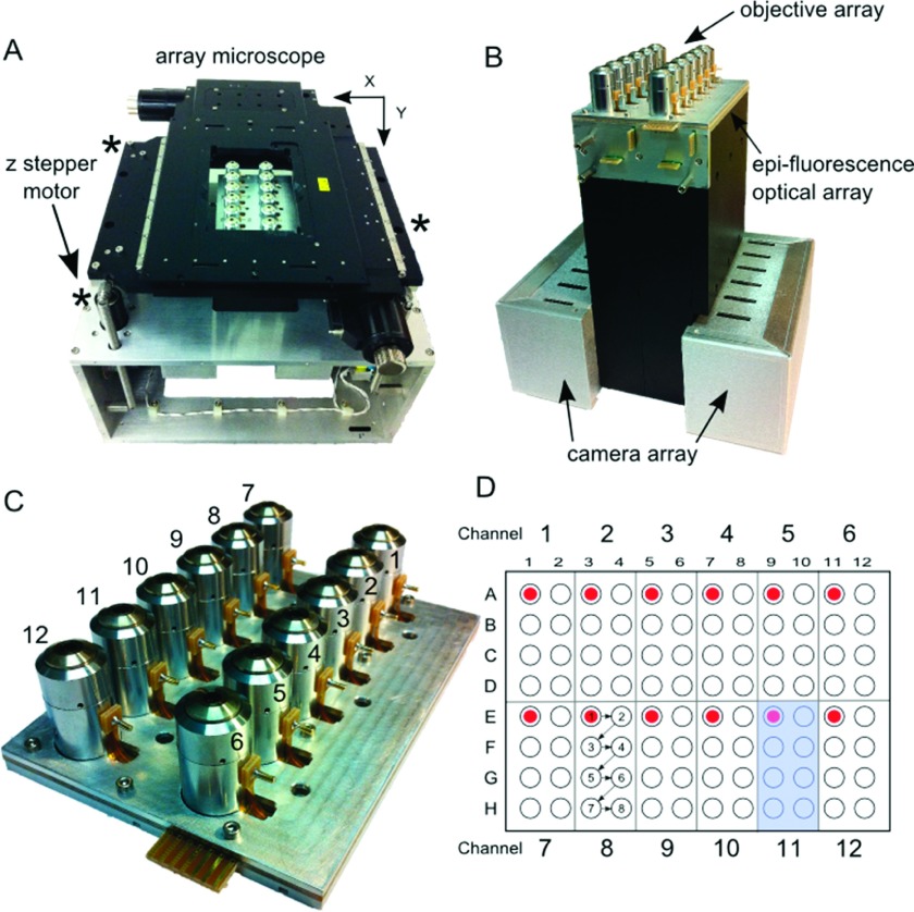
FIG. 1.
The AHT microscope. (a) System: In the center of the photo are the 12-objective lenses that sit beneath a 96-well multiwell plate (not shown). The objectives are surrounded by the XY-positioning stage. Three individually controlled stepper motors (marked by asterisks) drive the XY stage and multiwell plate in Z and compensate for tilt. The entire system is about the size of a breadbox. (b) The AHT imaging block. Beneath the 12-objectives are 5 printed circuit boards that supply voltage to the liquid lenses and current to the amber and blue LEDs that provide epi-fluorescence illumination. At the bottom of the imaging block are the control boards for the 12 cameras. (c) The objective array. The objectives are anchored between a support plate and an objective clamping plate. Each objective has a pin that supplies voltage to its liquid lens. (d) This schematic of a multiwell plate shows the neighborhood of wells visited by each of the 12 imaging channels (example shadowed in blue for channel 11). In a typical experiment, each channel starts in the upper-left corner of its neighborhood and follows the sequence shown in the figure for imaging channel 8.

