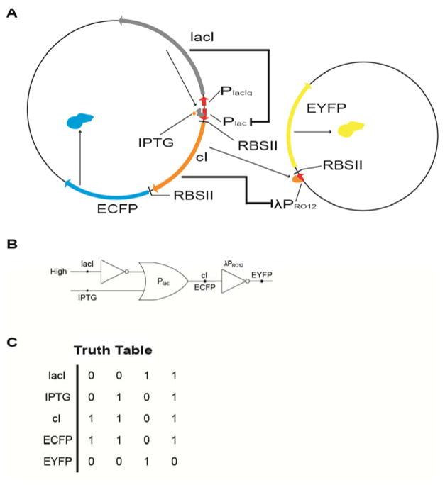
Figure 4.
(a) Design of the gene circuit. The expression of the CI repressor and ECFP was controlled by IPTG and the lac repressor. EYFP expression is repressed by CI. (b) The gene circuit represented by elementary logic gates. Plac acted as an “IMPLIES” gate while λPPRO12 acted as an inverter. (c) Truth table of the logic circuit.40

