
Figure 1.
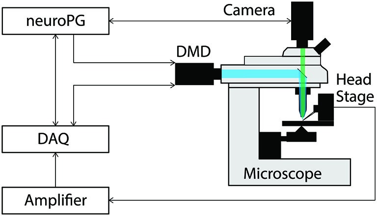
Connection diagram for the example procedures discussed in this paper. The DMD output trigger and the signal measured by the head stage are recorded as analog signals by the DAQ to facilitate precise temporal alignment between stimulation and response in the experiment. The DAQ signals the DMD using timed TTL pulses as configured by NeuroPG. All connections with NeuroPG are bi-directional, digital signals. The blue beam represents excitation light reflecting off the DMD and the green beam represents light fluorescently emitted from the sample.