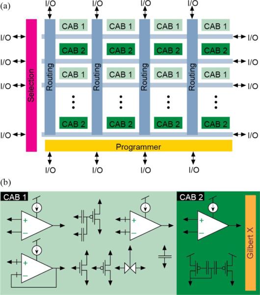
Fig. 2.
Floating-gate FPAA architecture. (a) The FPAA consists of an 8 × 4 matrix of computational analog blocks (CABs) interconnected through crossbar networks. (b) CAB1 contains three operational transconductance amplifiers (OTAs), three floating capacitors (500 fF), two multi-input floating gates, a voltage buffer, a transmission gate, and nMOS/pMOS transistor arrays. CAB2 has two folded Gilbert multipliers and a floating gate current mirror, and a wide-linear-range OTA. I/O signals are routed to the rows and columns of the switch matrix [13].

