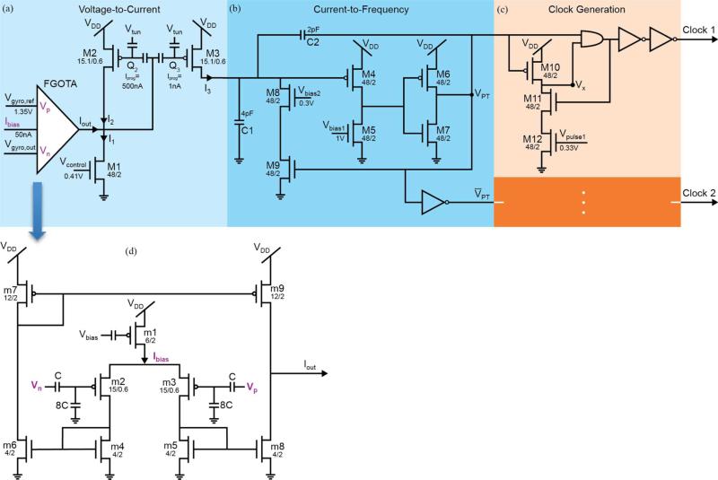
Fig. 4.
Circuit schematic of the signal processor. The bias voltages Vgyro,ref, Vcontrol, Vbias1, Vbias2, Vpulse1 and Vpulse2 are generated using an off-chip DAC housed on a development board. (a) The voltage-to-current converter block transfers the voltage signal from the gyroscope, Vgyro,out, into a current signal, I3. The current I3 is related to angular velocity through a tanh function. The minimum level of I3 is controlled by Vcontrol. By adjusting Vgyro,ref an offset can be added to Vgyro,out. This serves to translate the I3 along the x-axis of the I3 versus Vgyro,out curve. (b) The current-to-frequency converter block converts the current signal, I3, into the pulse train output VPT. Linearly related to I3, the frequency of VPT determines fstim. (c) Two similar fully digital Clock Generation stages create Clock 1 and Clock 2. The pulse width of Clock 1 is controlled by Vpulse1 and a similar relationship exists for Clock 2. (d) The FGOTA is the core of the voltage-to-current converter block. In the sub-threshold region, the output current, Iout, of the FGOTA is related to its differential input voltage, Vp-Vn, through a tanh function Ibias. is the bias current which determines the region of operation and is set up during the programming stage by Vbias.

