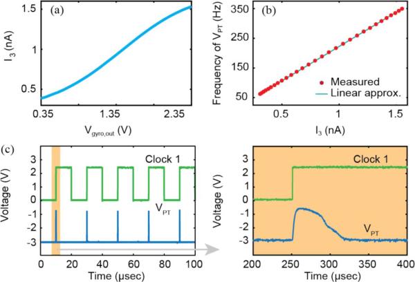
Fig. 7.
Summary of signal processor block level outputs. (a) Non-linear response to Vgyro,out generated by the voltage-to-current conversion block. (b) Linear fstim versus I3 response is exhibited by the current-to-frequency conversion block with thigh = 200 μs. (c) Triggering of Clock 1 by the rising edge of VPT. Note that a long (10 ms) clock pulse was created in the clock generation block to illustrate the relationship between the rising edge VPT of and Clock 1. In practice the pulse duration of Clock 1 would be less than the duration of VPT.

