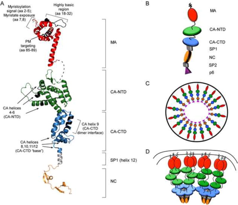
Fig. 2. Models for the structure of HIV-1 Gag domains and the architecture of the immature capsid.
(A) Ribbon diagrams of myristoylated MA in red (1UPH.pdb); full-length CA (3NTE.pdb) based on crystal structures of the individual CA-NTD and CA-CTD domains, shown in green and blue, respectively; SP1 (hypothetical α-helix) shown in grey, and NC (1mfs.pdb) shown in orange. Regions that contain residues critical for immature capsid assembly (shown in Fig. 1B) are indicated with brackets or arrows. Black highlights show locations of relevant amino acids. Dotted line shows flexible linker between MA and CA. (B) Schematic of full-length Gag as shown in Figs. 2C and D, with each domain labeled. (C) “Beads on a string model” for the arrangement of the Gag polyprotein in the immature capsid, adapted from (Fuller et al., 1997; Ganser-Pornillos et al., 2008; Yeager et al., 1998). (D) Model showing a hexameric configuration for CA-NTD, CA-CTD, and SP1 in the context of the fully assembled immature capsid lattice at the PM, adapted from (Wright et al., 2007).

