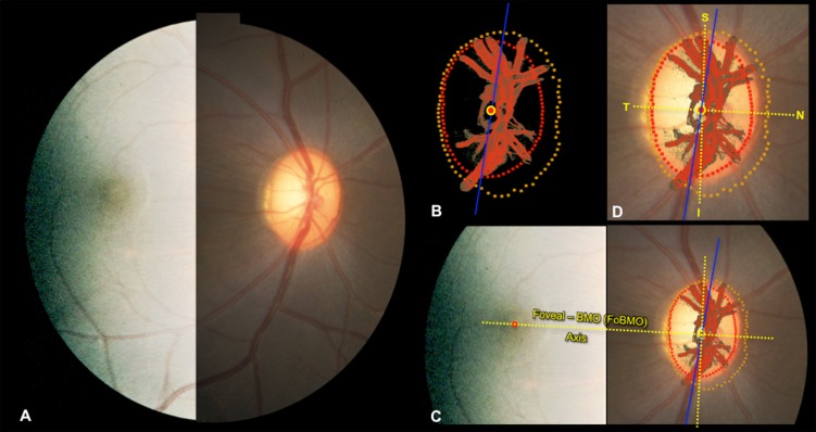
Figure 2.
Estimating the foveal-BMO (FoBMO) axis within the 3D HMRN BMO reference plane of each ONH. (A) A fundus photo (here with brightness enhanced temporally to better show the fovea), confocal scanning laser reflectance image26 (not shown), or postmortem fundus photo (not shown) was used to establish the axis between the fovea and the centroid of BMO for each eye as follows. (B) Delineated neural canal point clouds (BMO, red; ALI, dark yellow) and surfaced central retinal vessels (red) accompanied by the BMO centroid (red circle with yellow outline) and the embedded tissue block vertical (blue line) orientation were colocalized to the clinical fundus photo (C) using the vascular tree and BMO points (see Methods; in this image BMO reference plane is slightly rotated out of the plane of the image to enhance visualization). The center of the fovea ([C] red dot) is assigned to be the center of the dark foveal reflex or the center of the foveal capillaries. The axis connecting the center of the fovea to the BMO centroid (yellow with red center) is the FoBMO axis (C). Using the FoBMO axis as the nasal-temporal (horizontal) midline, a FoBMO vertical axis was established perpendicular to it (C), allowing anatomically consistent, FoBMO superior, inferior, nasal, and temporal landmarks (D) within the BMO reference plane of each studied eye to be established. In this study, LMA was characterized relative to a reference plane based on the anterior LC insertion points (rather than BMO). The FoBMO vertical and horizontal axes were thus projected from the BMO reference plane to the ALI reference plane at the time of cylinderization (see Fig. 5 and Methods). Finally, unlike SDOCT, in which both the FoBMO centroid and foveal center can be determined within SDOCT anatomy at the time of image acquisition, the FoBMO axis within our 3D HMRNs is an estimate because the fovea is not included within the ONH trephine.

