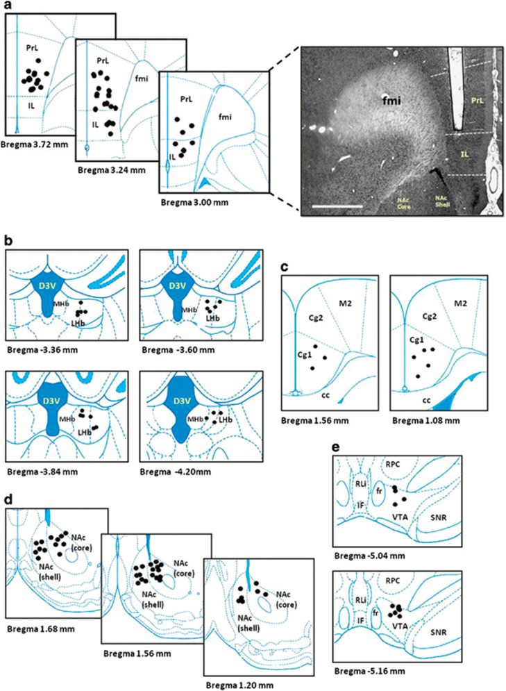
Figure 1.
Schematic illustration of the anatomical placement of stimulating electrode in the vmPFC (a), LHb (b), Cg (c), NAc (d) and the VTA (e). Photomicrograph of a 30-μm-thick coronal section from the brain of a rat showing the histological verification of the electrode location in the vmPFC (scale bar, 1 mm). The symbol ( ) indicates the tips of all electrode localization. cc, corpus callosum; Cg1 and Cg2, cingulate cortex 1 and cingulate cortex 2; D3V, dorsal third ventricle; fmi, forceps minor of corpus callosum; fr, fasciculus retroflexus; IF, interfascicular nucleus; IL, infralimbic; LHb, lateral habenular nucleus; MHb, medial habenular nucleus; M2, secondary motor cortex; NAc core, nucleus accumbens core; NAc shell, nucleus accumbens shell; PrL, prelimbic; RLi, rostral linear nucleus of the raphe; RPC, parvicellular part of the red nucleus; SNR, reticular part of the substantia nigra; vmPFC, ventromedial prefrontal cortex; VTA, ventral tegmental area.

