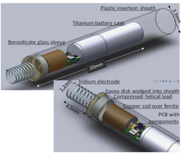
Figure 1.
Solidworks model of the rechargeable micropacemaker within plastic insertion sheath. (Features from left to right: corkscrew electrode (0.150mm Ir with Parylene-C insulation), epoxy disk over welded joint, flexible lead ( 0.075mm Pt-20Ir with Parylene-C insulation), glass sleeve for epoxy encapsulation, ferrite with 0.075mm copper inductive coil, printed circuit board with discrete surface-mount circuitry, and battery case of lithium cell, which functions as a return electrode. The subassembly consisting of the flexible lead and cork-screw electrode is fabricated separately and insulated with vapor-deposited Parylene-C except for the exposed portion of the iridium electrode, which is masked during deposition by embedding it in clay. The proximal end of the flexible lead is resistance welded to the exposed cross-section of a platinum rod that extends through the hollow ferrite; the weld is reinforced with an overcoat of the epoxy.)

