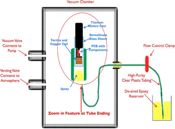
Figure 4.
Epoxy injection molding system. (The vacuum pulls air from the electronics and tubing through the slip fit between the titanium battery case and the brocosilicate glass sleeve. When the flow control clamp is opened, epoxy flows slowly around the ferrite and copper coil and covers the printed circuit board (PCB) and electronic components and battery terminals. Flow is clamped before the epoxy flows out past the glass sleeve. The epoxy is cured in place initially at room temperature and then post-cured in an oven.)

