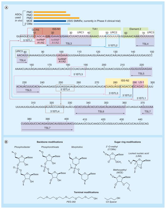
Figure 4. Linear representation of the entire SMN2 intron 7 (see facing page).
(A) Colored boxes designate the structural elements and splicing cis-elements. Numbering starts from the first position of intron 7. Double arrow within a given box indicates a TSL, whereas, a double arrow outside of boxes in the corresponding color shows the 5′ and 3′ strands of a particular ISTL. ISS-N1-targeting ASOs used for in vivo studies are shown as bars. The linear structure is adapted from [92]. (B) Chemical structures for a ASO backbone (unmodified phosphodiester, phosphorothioate and morpholino) and sugar ring modifications (2′-O-methyl, 2′-methoxyethyl and locked nucleic acid). The terminal modifications shown, PEG-282 and C3 spacer, were successfully utilized to increase the in vivo stability of a short ASO [99].
ASO: Antisense oligonucleotide; GCRS: GC-rich sequence; ISTL: Internal stem formed by LDI; LDI: Long-distance interaction; TSL: Terminal stem-loop; URC: U-rich cluster.

