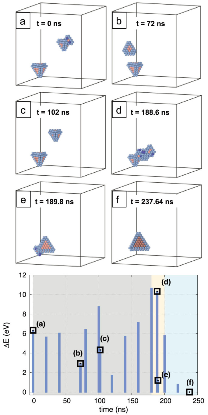
Figure 4. Reaction between a 15-V SFT and a 13-V SFT.

(a) Initial configuration; (b) and (c) the 13-V SFT migrates randomly in the system until it encounters the 15-V SFT; (d) SFTs react forming an unstructured complex; (e) the complex rearranges itself to form a defective SFT; (f) the defective SFT finds the minimum energy configuration forming a perfect 28-V SFT. The bottom plot shows the evolution of the energy relative to the final configuration (blue bars) with black squares referring structures (a) to (f). In the gray area the SFTs diffuse randomly, in the yellow region the reaction takes place and in the blue zone the perfect 28-V SFT is formed.
