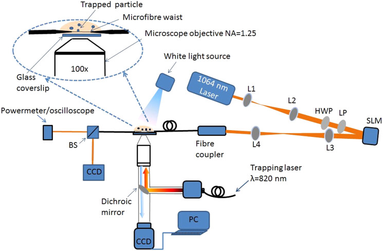
Figure 5. Experimental setup for particle propulsion.
L1, L2, L3, L4 are lenses, LP and HWP are a linear polariser and a half wave plate, respectively, BS is a beam splitter, CCD is a camera and PC is a computer. The red lines represent the free beam path. The inset shows the magnified image of the interaction region.

