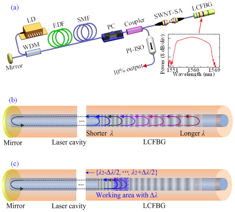
Figure 1. Set-up of DUF fibre laser.
(a) Cavity setup of the PML fibre laser incorporating a linearly chirped fibre Bragg grating (LCFBG). Inset: Reflection spectra of LCFBG. The LCFBG is spliced in a linear cavity containing a single-walled carbon nanotube (SWNT) saturable absorber (SA) to mode-lock ultrafast laser, a polarisation controller (PC) to act on the pulse polarisation and adjust the central wavelength, a gain fibre (EDF), a wavelength-division multiplexer (WDM) to couple the pump source (LD), and a high-reflecting dielectric mirror. A polarisation independent isolator (PI-ISO) forces the unidirectional output of the laser. The total length of linear cavity is ~17.7 m with ~7-m-long EDF and ~15-mm-long LCFBG. (b) Schematic diagram of the LCFBG-based fibre laser. The LCFBG reflects the different wavelengths with respect to its position. Round-trip distance for a pulse with a shorter wavelength is less than that for a pulse with a longer wavelength. (c) The operation of ultrafast fibre laser with the central wavelength of λ2 and the spectral bandwidth of Δλ. The blue area of the LCFBG reflects the spectra from λ2 − Δλ/2 to λ2 + Δλ/2. The different spectral components of the pulses propagate through the different distances in a round trip.

