
Fig. 5.
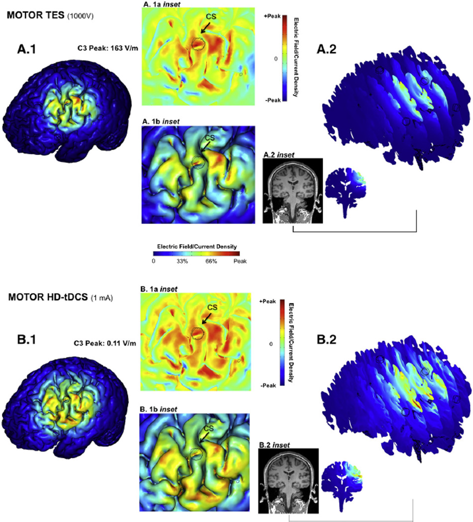
High-resolution computer simulation prediction of relative focality of Transcranial Electrical Stimulation (TES) and transcranial Direct Current Stimulation (tDCS) using the High-Definition 4×1 Ring Configuration. Using the identical High-Definition 4×1 electrode montage centered on C3, the relative brain stimulation focality using a high-voltage short-pulse (TES, A, same conditions as Fig. 2 plotted full scale) and low-intensity direct current (tDCS, B) was calculated (see Methods). In each case, the resulting cortical electric field magnitude is plotted relative to the respective peak cortical electric field induced for each waveform: 163 V/m for TES, and 0.11 V/m for tDCS. The false-color maps thus indicate the spatial distribution of brain stimulation and relative focality in each case. For both TES4×1 and tDCS4×1: 1) The relative brain surface activation (>30% peak) was generally restricted to inside the ring (A.1, B.1) but the relative spatial distribution was slightly broader for tDCS; 2) The electric field was slightly more superficial for the TES4×1 waveform (A.2, B.2); 3) The peak cortical electric field (A.1b inset, B.1b inset) was on gyri crowns, interestingly in both cases on the same gyrus slightly posterior to the center electrode; 4) Consideration of normal direction current (A.1a inset, B.1a inset) red: inward; green: no normal current; blue: outward) did not change the above findings.