Abstract
We present a new semi-automatic processing method for retinal nerve fiber bundle tracing based on polarization sensitive optical coherence tomography (PS-OCT) data sets. The method for tracing is based on a nerve fiber orientation map that covers the fovea and optic nerve head (ONH) regions. In order to generate the orientation map, two types of information are used: optic axis orientation based on polarization data, and complementary information obtained from nerve fiber layer (NFL) local thickness variation to reveal fiber bundle structures around the fovea. The corresponding two orientation maps are fused into a combined fiber orientation map. En face maps of NFL retardation, thickness, and unit-depth-retardation (UDR, equivalent to birefringence) are transformed into “along-trace” maps by using the obtained traces of the nerve fiber bundles. The method is demonstrated in the eyes of healthy volunteers, and as an example of further analyses utilizing this method, maps illustrating the gradients of NFL retardation, thickness, and UDR are demonstrated.
OCIS codes: (170.0170) Medical optics and biotechnology, (170.0110) Imaging systems, (170.2655) Functional monitoring and imaging, (170.4470) Ophthalmology, (170.4500) Optical coherence tomography
1. Introduction
The retinal nerve fiber is the axon of a retinal ganglion cell (RGC), consisting of axonal membranes, microtubules, neurofilaments, and mitochondria [1–3]. It is one of the major building blocks of the human visual system, carrying the visual information and transferring the signals from cone and rod photoreceptors via an RGC to the brain through the optic nerve head (ONH). Signal loss caused by nerve fiber defects leads to a possible loss of vision at a certain location of the visual field [4]. In that sense, investigation and thorough understanding of structure and function of retinal nerve fibers, fiber bundles, and fiber layers are very important as one of the fundamentals of the visual system.
The thickness of an individual retinal nerve fiber is about 0.1 – 4 μm, and typically 300 ~20000 nerve fibers are congregated as a nerve fiber bundle [1–3,5]. The bundle thickness and width range about 10 – 60 μm [6]. The distribution of the nerve fiber bundles is basically radial at the circum-papillary regions (i.e., around the ONH), and the striations of fiber bundles from the temporal part of the ONH mostly flow into the foveal region where a group of striations converge at the foveal center and the others divert themselves from the center to reach further distant temporal positions. In the superior, nasal, and inferior directions, the fiber bundle striations are basically radial and bend toward the temporal direction where they flow away from the ONH (note that in this paragraph, the terms, flow and divert, are used only to illustrate the shapes and positions of the fiber bundles and do not mean either the direction of neural signal nor the direction of growth of the optic nerve) [1,7–9]. The retinal layer which contains the nerve fiber bundles is the retinal nerve fiber layer (NFL), which is located at the surface of retina, posterior to the inner limiting membrane (ILM), and anterior to the retinal ganglion cell layer. The thickness of the NFL ranges from about 10 μm (around the fovea) to 400 μm (margin of the ONH) for a healthy human eye [10]. In case of glaucoma, one of the major eye diseases leading to blindness [11], the NFL thickness is reduced.
The pathological process of glaucoma starts with axonal injury at the ONH followed by degeneration and apoptosis of RGCs, loss of retinal nerve fibers, and thinning of NFL [12]. Although clinically established treatment modalities currently available can prevent or reduce the speed of progress of such damage, they are not yet capable of repairing the RGC axonal loss resulting in lost connections to the central visual system; therefore, early diagnosis of the disease is crucial. Thus, tools and techniques which enable monitoring and quantification of early signs and progression of the structural and functional changes efficiently and accurately are greatly desired.
Visual functions and their relationship to the structural changes in glaucomatous retina, including those in early phases, have been monitored and investigated widely [7,9,13–15]. One of the key issues to achieve reliable analyses in those studies is mapping between the visual function measured by visual field analyzer with typical test patterns (e.g., Humphrey 24-2 [15,16]) and the structural changes measured by confocal scanning laser ophthalmoscope (cSLO) [17] and/or optical coherence tomography (OCT) [18]. The corresponding locations of the former are distributed widely and centered at the macular region, and those of the latter are centered at the optic nerve head (ONH) region [18–20]. Relationships between structural data sets in the macular and the peripapillary region have also been investigated. Hood et al. (2013) [9] have shown that the asymmetry of visual field defects in early glaucoma, affecting the superior visual field stronger than the inferior field, is associated with a loss of retinal ganglion cells in the inferior macula and a thinning of the NFL in a narrow “macular vulnerability zone” (MVZ) located infero-temporally of the ONH. Accurate mapping of the nerve fiber bundle traces, which connect the two regions physically and functionally, is indispensable for the basis of such studies [7,15]. Such fiber bundle tracing, identifying, in a histological sense, the nerve fiber bundles which connects the two regions physically and functionally, could shed more light into the circumstances and development of early glaucoma.
Methods and techniques for tracing of the nerve fiber bundle striation in human retina, previously reported, can be categorized into the following: (i) manual tracing by a grader in en face fundus images, (ii) computational segmentation in en face fundus images, (iii) mathematical modeling with parameter fitting, (iv) step by step tracing by a computational simulation of nerve fiber growth based on RGC density data. (i) and (ii) are based on en face images of the retina recorded by, e.g., cSLO [21] or red-free blue filter fundus photography [22]. The images are typically processed, prior to the tracing, to enhance the visibility of the striation of the nerve fiber bundle, such as by selection of high quality images, by multiple frame averaging with image registration, and by spatial filtering and/or color balance adjustment. (iii) is based on analytical models which involves fitting by a few parameters (e.g., two or three parameters are used [8,23–25]). The fitting is conducted by using en face images acquired by fundus photography [8,23,24], or by using visual field data [25]. (iv) is based on an algorithm in which the RGC density is the factor directing the trace [26].
For a tracing technique to be practical, it needs to be automatic or at least semi-automatic, robust (e.g., applicable to wide range of targeted eyes, and resistant to changes across to imaging conditions), and sufficiently accurate. Models using only a few fitting parameter are simple enough to be implemented as an automatic tracing system. On the other hand, they have potential difficulty to accurately characterize wide range of targeted retinas and nerve fiber bundle striation patterns. Methods based on reflective images have potential susceptibility to imaging conditions such as a variation of the retinal illumination due to eye motions. Although robust and accurate estimation seems possible, (iv) needs density information of RGC that is not easily available by OCT or other in-vivo imaging modalities.
Polarization sensitive optical coherence tomography (PS-OCT) is a functional extension of OCT [27–33], by which tissue specific contrast is available with regard to its polarization properties, e.g., polarization-preserving, birefringent, or depolarizing characteristics. The ability of PS-OCT enables researchers to analyze, e.g., the birefringent NFL and Henle’s fiber layer, as well as the retinal pigment epithelium (RPE) with depolarizing properties, and to segment these layers from polarization preserving layers, e.g., ganglion cell layer (GCL), inner plexiform layer (IPL), inner nuclear layer (INL)) [34–41].
In ophthalmic applications of PS-OCT [42], especially for glaucoma studies, assessment of retardation and birefringence of the NFL is of great importance. The birefringence of the NFL originates from the nerve fibers and their constituents, e.g., microtubules having a cylindrical structure with a thickness of about 10 – 30 nm [3,43]. While retardation of the NFL is already widely used to estimate the NFL thickness for glaucoma diagnostics by scanning laser polarimetery (SLP) [44], recent studies in animal models of experimental glaucoma have shown that the birefringence is reduced before any onset of NFL thinning is measurable [45]. These findings indicate that NFL birefringence analysis might be of great interest for glaucoma diagnostics. While the new findings stimulate further investigations, it should be mentioned that the SLP technology has not been yet successful to supplant OCT in glaucoma diagnostics; among previous clinical reports comparing NFL retardation and thickness measured by SLP and OCT, respectively, for early glaucoma diagnostics, there is still no evidence that NFL retardation is superior to NFL thickness in detecting early glaucoma or measuring glaucoma progression. The primary parameters obtained by PS-OCT are phase retardation and optic axis orientation. By virtue of its depth-resolving ability, PS-OCT enables direct pixel to pixel correspondence between retardation and depth position, and birefringence can be obtained by linear regression analysis along the depth in the NFL [34,35,46–48]. The other parameter, axis orientation, in NFL carries the information about the orientation of the nerve fiber bundles, which means that nerve fiber bundle tracing by axis orientation is basically possible.
In this paper, we present a new semi-automatic processing method of retinal nerve fiber tracing based on PS-OCT data sets. The method uses two types of information to obtain nerve fiber bundle maps: (i) in the regions with thick NFL around the ONH, axis orientation derived from polarization data is employed, (ii) in the thin NFL regions around the fovea, where the polarization based axis orientation information is unreliable, thickness data are used. The maps from the two regions are finally fused into a combined fiber orientation map to allow for nerve fiber bundle tracing from ONH to regions including the center of the fovea. En face maps of retardation, NFL thickness, and unit-depth-retardation (UDR, defined by the retardation divided by the NFL thickness and representing birefringence) are transformed into “along-trace” maps by using the obtained traces of the nerve fiber bundles. The method is demonstrated in the eyes of healthy volunteers, and as an example of further analyses utilizing this method, maps illustrating the gradients of NFL retardation, thickness, and UDR are presented.
2. Methods
A spectral domain (SD) PS-OCT instrument with an integrated retinal tracker [49] was used for imaging of human retina in-vivo. The PS-OCT subsystem utilizes polarization maintaining (PM) fibers and illuminates the sample with a single, circular polarization state [50]. A superluminecsent diode light source with a center wavelength of 860 nm and a spectral width of 60 nm was used. Two spectrometers equipped with CMOS line-sensor cameras recorded the interference signals in frequency domain for two orthogonal polarization states. A line-scanning SLO (LSLO) was used for acquiring en face images to provide position information for the retinal tracker. The LSLO uses a laser light source of 785 nm wavelength. The power to the eye was 0.4 mW from the LSLO and 0.6 mW from the PS-OCT. This is below the safety limit for combined exposures drawn by International Electrotechnical Commission (IEC) [51]. The measured sensitivity of the PS-OCT was 98 dB near the zero-delay depth position. The PS-OCT operates at 70 kHz A-scan rate, and a single 3D volume consisting of 1024 (x) × 250 (y) A-scans (FOV: 28° × 21°) was recorded in 4.5 s.
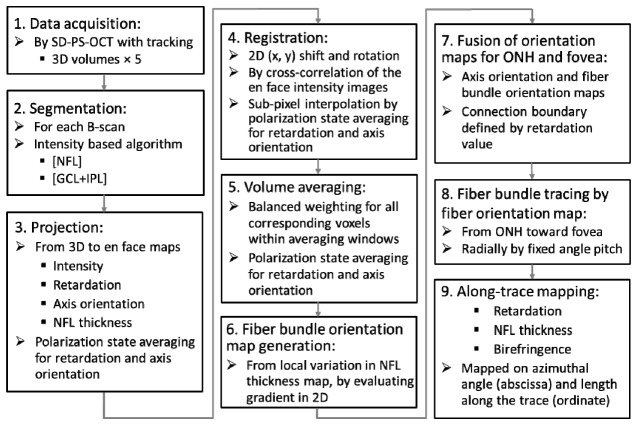
Figure 1 shows the data acquisition and processing steps, the details of which are explained in the following.
Fig. 1.
Data acquisition and processing steps.
Step 1. Data acquisition: Multiple 3D volume data acquisition was conducted, where five volumes were recorded for each subject eye.
Step 2. Segmentation: For each B-scan image, three boundaries, the inner limiting membrane (ILM), the interface between NFL and ganglion cell layer (GCL), and the interface between inner plexiform layer (IPL) and inner nuclear layer (INL) were detected by an intensity-based segmentation algorithm consisting of several sub-processing steps (Fig. 2(a) ): For the first sub-step, binarization is performed by an evaluation window (9 (x) × 6 (z) pixels) sliding over a B-scan image. The choice of this window size is based on our empirical experience in previous work; it tries to find a proper balance between the trade-offs of a sufficient pixel number for averaging and maintenance of a reasonable spatial resolution, in this case, 70 (x) × 8 (z) μm2.
Fig. 2.
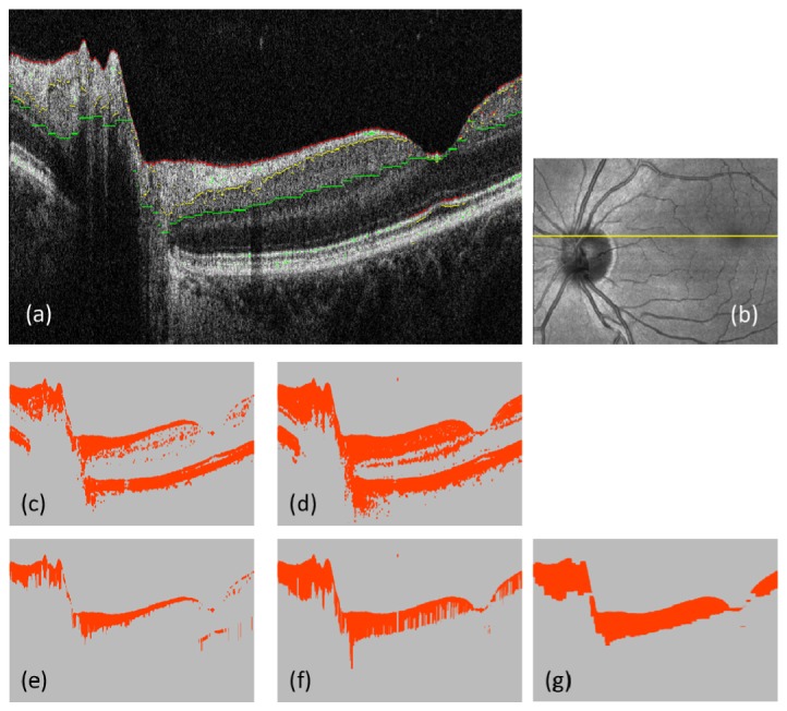
Segmentation of ILM, NFL/GCL and IPL/INL interfaces. (a): Intensity B-scan; red, yellow, and green pixels indicate the segmented boundaries of ILM, NFL/GCL and IPL/INL. (b): Intensity projection; yellow line indicates the position of B-scan. (c) and (d): Binarization results; using intensity thresholds (3.7 for (c), and 3.9 for (d) in log10 scale); orange color: foreground pixels, gray color: background pixels. (e) and (f): Uppermost connected sets of the foreground pixels along each A-scan; processed from (c) and (d), respectively. (g): Result of applying a series of morphological image processing (cascaded dilations and erosions) to (f).
If more than 7 pixels within the window at a pixel position have intensities above a set threshold value, the pixel is classified as foreground (orange color in Figs. 2(c), 2(d)). The threshold values for segmenting the ILM and the NFL/GCL interface (Figs. 2(c), 2(e)), and the IPL/INL interface (Figs. 2(d), 2(f)), were set at 6 dB, and 8 dB, above the mean noise level, respectively.
For the next sub-processing step after generating the binary images (e.g., Figs. 2(c), 2(d)), the uppermost connected sets of foreground pixels along each A-scan were detected (Figs. 2(e), 2(f)): in each A-scan, the foreground pixels were checked from the top position (i.e., ILM) of the B-scan image stepping toward the deeper side, monotonically, until reaching an edge where a background pixel exists in the next position, and the pixels below the edge were designated as background (gray color).
For the IPL/INL interface detection, an additional morphologic image processing step was applied in order to suppress artifacts generated mainly by blood vessels. The process is a sequence of 8-pixel dilation, 16-pixel erosion, and 8-pixel dilation, where the dilating/eroding direction is only horizontally; this is because the artifacts (e.g. shadowing by a blood vessel) are vertically extended (see Fig. 2; the transition from 2(f) to 2(g).) The number of pixels available for averaging is increased by this step from about 21000 to 27000 pixels ( + 29%) in the right half of the B-scan image (i.e., the foveal region where the vessel shadows are frequent), as an example of the improvement from Fig. 2(f) to 2(g).
Resulting foreground pixels by the two thresholding conditions represent NFL and NFL + GCL + IPL, respectively (Figs. 2(e), 2(g)), and three boundaries: the inner and outer edge of the segmented NFL (e.g. red and yellow pixels in Fig. 2(a)) and the outer edge of the segmented NFL + GCL + IPL (e.g., green pixels) were used for further processing.
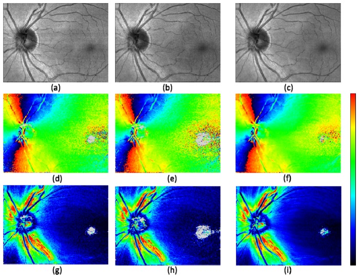
Step 3. Projection: In this sub-processing step, an intensity projection map and retardation and axis orientation maps were generated for each 3D volume. The intensity projection map is generated by averaging the intensities (in linear scale) over all pixels in depth for each A-scan. Sample projection images obtained by this step are shown in Fig. 3 .
Fig. 3.
Projected en face maps from a healthy volunteer after registration. Intensity projection (a) – (c); axis orientation (d) – (f); retardation (g) – (i). The best quality frame (a), (d), (g); the lowest quality frame (b), (e), (h); averaged frame (c), (f), (i) out of 5 volumes. Color scales: −90° – + 90° for axis orientation, and 0° – 30° for retardation. Gray pixels indicate having too low number of segmented voxels for evaluation.
Prior to projection of the retardation and axis orientation, a computational compensation for polarization change caused by anterior segment was performed for each B-scan frame by the method described in [52], Pircher et al. (2007). By this compensation and the compensation for PM fibers included as a signal processing step of the PM fiber based SD-PS-OCT described in [50], Götzinger et al. (2009), polarization and axis changing effects from the anterior segment (e.g., the cornea) and the PM fibers were removed.
In generating the retardation and axis orientation maps, a sliding average window of 6 (x) × 2 (y) pixels was used. Along each A-scan within the window, pixels residing within the depth range from the NFL/GCL interface to the IPL/INL interface, segmented in the previous step, were selected for polarization state averaging (so averaging was performed in 3D, across the xy window and within the specified depth range).
This depth range corresponds to the polarization maintaining layers after the sample beam passed through the birefringent NFL and before the beam reaches Henle’s fiber layer (HFL), which is also birefringent. This ensures that only the birefringent effect of the NFL is included in the further evaluation steps. By averaging polarization states of the pixels in this depth range rather than just extracting the polarization state of the pixel at NFL/GCL interface, an improved signal-to-noise ratio can be obtained. (Taking average over pixels within specifically targeted retinal layers for improved signal-to-noise ratio for better evaluation of the characteristics in a region of interested has been presented in previous publication [41].) In this work, the analysis of the birefringent effect of the NFL is restricted to the averaged birefringence (UDR) over the entire depth of the NFL. When the number of pixels in each of the A-scans to be averaged is less than 5 (including the case of negative value, meaning an obvious segmentation error), the corresponding A-scan is disqualified and excluded from the calculation. When no qualified pixel (voxel) for averaging remains within the window, the pixel under evaluation is designated as background and not used for further calculation (displayed in gray color, e.g., in Figs. 3(d)-3(i)).
The polarization state averaging used in this study is based on the Stokes vector averaging with re-normalization (see Appendix A).
Next, NFL thickness maps were generated. Within the same averaging window (i.e., 6 × 2 pixels in xy) as used for the retardation and axis orientation maps, depth ranges from the ILM to the NFL/GCL interface (e.g. the number of pixels in each A-scan in Fig. 2(e), based on the segmentation by the intensity data) were averaged.
Additionally, a map of the number of averaged voxels within each sliding average window was also generated and stored for later processing steps.
Step 4. Registration: Among the five OCT intensity projection en face maps recorded in each eye, registration based on cross-correlation was performed. As a pre-process, interpolation in y-direction was conducted to form isotropic sampling in x and y directions, and the number of pixels in y-direction for the en face maps was increased from 250 to 768 pixels. In a next processing step, the map from the first of the five data sets was used for the reference (unless the quality was the worst among the five by visual check; in that case, another map having the best quality was chosen manually), and other images were registered.
To accommodate for residual in-plane distortions in the registration calculation, 12 strips, each of which consists of 1024 (x) × 192 (y) pixels, were located within each map, at equal intervals and with overlaps by 140 pixels in y-direction. 2D displacement and rotation angle for each strip position were detected by cross-correlation between the corresponding strips in the reference and the target maps. The detected displacement and rotation values were linearly interpolated for the 768 (y) pixel positions. The detected rotation angles range about a few degrees over the y-positions. These residual motion artifacts are not corrected by the retinal tracker, which is not capable of compensating cyclo-rotary motions (torsions) of the eye.
In this registration step, including image rotation, procedures of interpolation are required. For that purpose, linear interpolation using the nearest neighbor pixels (e.g., four pixels) was employed, where for obtaining the polarization state (i.e., for the retardation and axis orientation maps), weighted averaging was performed on the polarization states based on the Stokes vector averaging with re-normalization (Appendix A). The weighting for each of the four neighboring pixels is two-fold: (i) by the distances in x and y direction to the target pixel, (ii) by the numbers of voxels used to generate the map for each of the four pixels (stored in Step 3). Especially, by introducing the weighting factor (ii), a balanced contribution from the averaged voxels is achieved.
Step 5. Volume averaging: After the registration of the five maps, the polarization states and the NFL thickness values were averaged among the corresponding pixels. Here again, the weighting by the numbers of total voxels used to generate each map (i.e., the similar weighting as (ii) of Step 4) is employed in order to achieve a balanced contribution of the voxels averaged among the 3D volumes.
Step 6. Fiber bundle orientation map generation from NFL thickness data: In the axis orientation maps, it is observed that noisy pixels are prevalent in the foveal region (Figs. 3(d), 3(e)). Some of those still remain in the averaged map (e.g., Fig. 3(f)). The location corresponds to the region of low retardation, where the axis orientation is, naturally, susceptible to noise. While it would be possible to improve the signal-to-noise ratio by increasing the number of averaging frames and volumes, we found in this study that a complementary map, fiber bundle orientation map, can be extracted directly from the corresponding NFL thickness map without increasing the number of averaged volumes (i.e., from five 3D-volumes), and in this step, the noisy axis orientation in the foveal region was replaced with the fiber bundle orientation calculated from the NFL thickness map by fusion of the two maps.
The NFL thickness map, which is the result of averaging among five 3D volumes, is shown in Fig. 4(a) , where fiber bundles around the foveal region appear with observable contrast (light to dark blue colors). As the first pre-process in order to remove low spatial frequency components, an adaptive high-pass filter (i.e., subtracting local mean within 15 × 15 pixel window) is applied so that the local thickness variation is mapped more clearly (Fig. 4(b)). The local thickness variation is observed to contain typically two factors: nerve fiber bundles and blood vessels. Since the latter has wider range of thickness variation (e.g., white and gray colored pixels: more than + 15 μm and less than −8 μm, respectively), it can be effectively removed by thresholding as the second pre-process (Fig. 4(c)). This process, at the same time, removes some of the ridge and the valley pixels of the fiber bundle structures of interest. Those pixels are, however, less contributing to the detection of the fiber bundle orientation performed in the next process, which is using local gradient information (i.e., steepness of the thickness change) in the variation map. It is because the ridge and valley pixels have smaller local gradients (which are perpendicular to the fiber orientation) compared to the hillside pixels that reside in between the ridge and the valley; the hillside pixels have larger gradients representing the fiber structure in the thickness variation map.
Fig. 4.
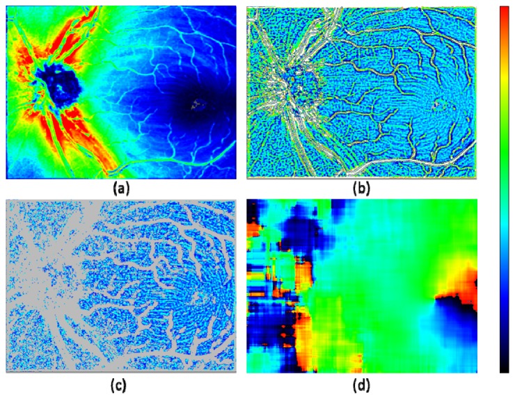
Fiber bundle orientation detection by NFL thickness map. (a): NFL thickness map; color scale: 0 – 180 μm. (b) Local thickness variation calculated by an adaptive filtering; color scale: −8 – + 15 μm (gray color: < −8 μm; white color: > + 15 μm). (c) Selected pixels from (b), having local thickness variation within −2 – + 2 μm range; a morphologic image processing (erosion and dilation by 1 pixel in both horizontal and vertical directions) was applied; color scale: −4 – + 9 μm (gray color: pixels excluded from processing). (d) Fiber bundle orientation calculated by local gradient of (c) within 120 × 120 pixel evaluation window; color scale: −90° – + 90°.
The fiber bundle orientation is extracted by the following two processing steps: (i) local gradient calculation in x and y direction, (ii) least square estimate of orientation by local gradients within an evaluation window. These processing steps are described in previously published articles for fingerprint recognition techniques [53,54]. In this study, simple Sobel filtering was employed for (i), and the evaluation window size for (ii) was configured to be 120 × 120 pixels. The resulting fiber bundle orientation map (Fig. 4(d)) shows smooth distribution in the foveal region, while distortions of the fiber bundle orientation are observed in the ONH region where less pixels are available due to the presence of thick blood vessels.
Step 7. Fusion of orientation maps for ONH and fovea: In Fig. 5 , the method of combining the two maps: the axis orientation map by PS-OCT and the fiber bundle orientation map by the NFL thickness is displayed. Since the noisy region in the former originates from low retardation polarization states, it is reasonable to use the retardation map to draw the boundary where the two maps are connected. Figure 5(c) is the retardation map averaged among five 3D volumes after low pass filtering by sliding average within a 15 × 15 pixel window. In x-direction from the fovea to ONH, the first pixels with the retardation value exceeding 5° and 7° were detected. The values 5° and 7° were chosen empirically. The detected x- positions as a function of y were smoothed by sliding average within 100 pixel window (in y-direction) and two boundaries for 5° and 7° were defined (black and white lines). In the fused fiber orientation map (Fig. 5(d)), the ONH region on the left side of the 7° boundary displays the axis orientation by PS-OCT, while the foveal region on the right side of the 5° boundary show the fiber bundle orientation by NFL thickness. In the transition zone in between the 5° and 7° boundaries, a linear interpolation between the two orientation values was used.
Fig. 5.
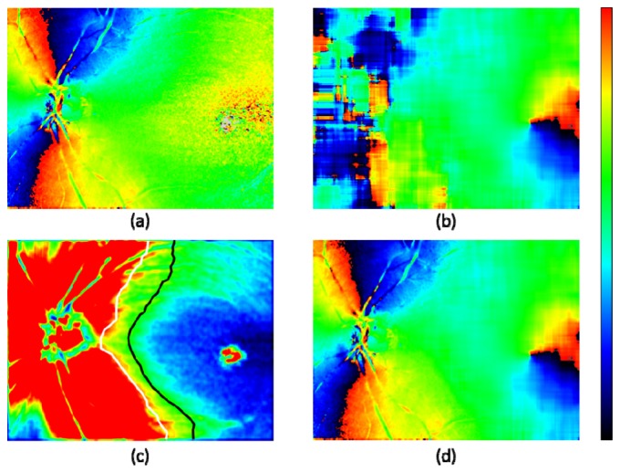
Fusion of ONH and foveal zone maps for fiber orientation. (a): Axis orientation obtained by polarization data from PS-OCT (5 frame averaged). (b): Fiber bundle orientation obtained by NFL thickness map. (c): Retardation; color scale 0° – 8°; white and black lines: boundaries of 7° and 5°, respectively. (d): Combined orientation from (a) and (b); low retardation zone with < 5° of (a) is replaced by corresponding zone of (b), and transition zone from 5° to 7° is linearly interpolated.
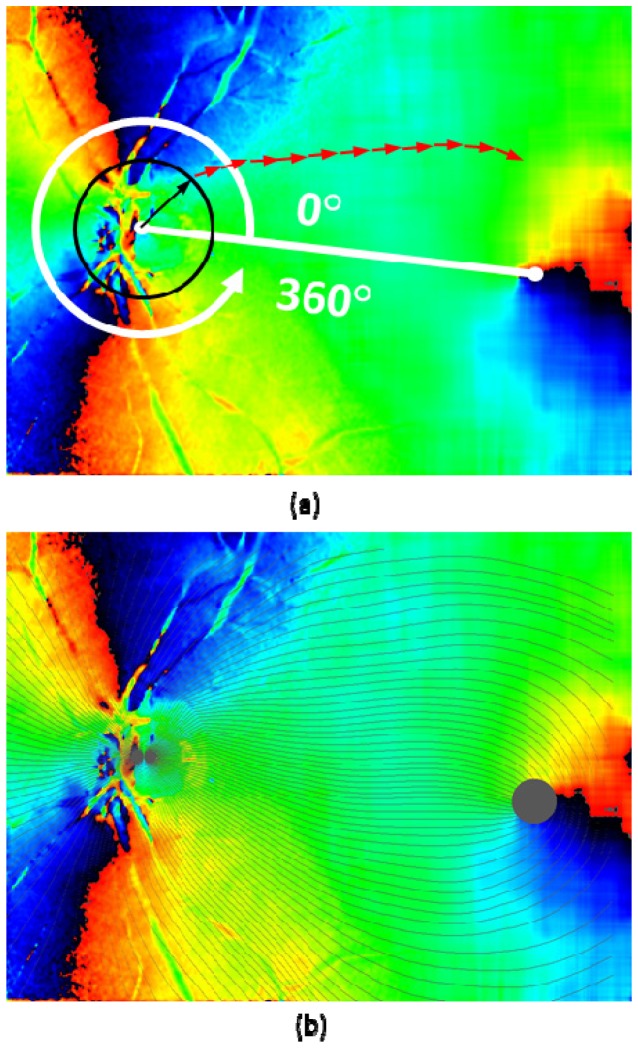
Step 8. Fiber bundle tracing by fiber orientation map: The final fiber orientation map obtained after the previous steps is used for tracing the nerve fiber bundles on the retina. First, the centers of ONH and fovea were manually designated. The starting points of the tracing were located on the perimeter of a circle centered at the ONH with one disc diameter (DD: defined as 6°), and arranged by an azimuthal angle pitch. For example, 1° pitch arrangement generates 360 tracing lines. From the starting point, vectors with a fixed length traced the local fiber orientations step by step (red arrows in Fig. 6(a) ; with a length of 0.035 mm (0.12°). The local fiber orientations were obtained at the starting position of each vector by the following algorithm: First, the fiber orientation map is segmented by 36 × 36 pixel sized blocks, and then, the fiber orientation values within each block were averaged. Next, depending on the starting position of the tracing vector, linear interpolation from the averaged values within the nearest neighbor blocks was performed.
Fig. 6.
Fiber bundle tracing by fiber orientation map. (a): Tracing process; black and red arrows overlaid on the fiber orientation map indicate the tracing steps (arrows are not in scale; length of black arrow: 0.5 DD, red arrow: 0.035 mm). (b): Traced lines (displayed in black color) with azimuthal angle of 3° pitch (120 lines) overlaid on axis orientation map.
The tracing of each (nerve fiber bundle) line was terminated either (i) when it reached the set maximum of steps, (ii) when it reached the foveal center region, defined as a circle area with a diameter of 2°, (iii) when the tracing line turns back to the ONH direction (judged by the direction of current vector against the sum of all the previous vectors), or (iv) when it reached an outer edge of the map. The result of tracing in a healthy eye (healthy eye A) is shown in Fig. 6(b).
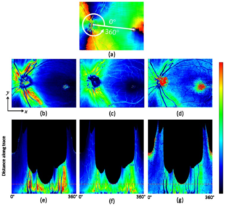
Step 9. Along-trace mapping: Retardation, NFL thickness, unit-depth-retardation (UDR, defined by the retardation divided by the NFL thickness) values were extracted at each tracing vector start/end point, and mapped on a coordinate system consisting of azimuthal angle as abscissa and distance along the trace as ordinate. From these maps, evolution and changes of the parameters along the fiber bundle trace from the ONH to the fovea can be observed more systematically and analyzed as a function of azimuthal angle.
In this study, four healthy eyes of two volunteer subjects were imaged. The study was approved by the university’s ethics committee, and conformed to the Declaration of Helsinki for research in human subjects.
3. Results
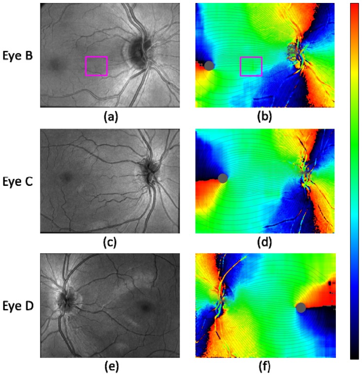
In Fig. 7 , the fiber bundle tracing results for three healthy eyes B, C, D are shown with corresponding OCT intensity projection images. Along with the result shown in Fig. 6(b), they illustrate that the fusion of PS-OCT axis orientation map and fiber bundle orientation map obtained from NFL thickness, and the tracing by the fused fiber orientation map was successfully performed for both right and left eyes of the two different subjects.
Fig. 7.
Fiber bundle tracing results for three healthy eyes B, C, D. (a), (c), (e): OCT intensity projection. (b), (d), (f): Fiber orientation maps with traced lines (azimuthal angle pitch 3° (120 lines)). Healthy eye B: (a), (b); healthy eye C: (c), (d); healthy eye D: (e), (f). Magenta rectangle in (a) and (b) indicates the area where a bundle orientation error exists due to thin vessels.
Two issues of the tracing results should be mentioned: The first observation concerns the temporal raphe [9,55]. Although the direction of the raphe is expected to align approximately (e.g., < 10° [7–9,22,23]) with the line connecting the fovea and the ONH (and directing slightly superior compared to the line when it diverts from the fovea), Fig. 7(b) appears to have a clear deviation (> 30°) when the boundary between black and red colored parts in the map extending from the fovea is regarded as the raphe. The black-red colored part, however, does not actually correspond to the raphe, since it only indicates that the bundle orientation is vertical in the instrumental frame. In the case of Fig. 7(b), the raphe is likely to be the dark orange colored part extending from the fovea and directing slightly inferior (speculated from e.g., Fig. 4(a)); in this case, the line connecting the fovea and the ONH is more inclined when compared with those in the cases of Figs. 7(d) and 7(f) (see Figs. 8(a) , 9(a) , 9(b), 9(c) in comparison), which leads to this inferior direction. Another aspect concerns a possible computational error which might be contained near the temporal raphe, which is caused by the relatively large evaluation window for the fiber bundle orientation calculation step, which extends 120 × 120 pixels. Although the imaged field-of-views were configured to include both the ONH and the foveal regions, the limited instrumental scan angle (27° in the x-direction) hampers to contain enough pixels at the temporal area to the fovea, which might have affected the results.
Fig. 8.
Fiber bundle tracing and maps along the trace in healthy eye A. (a): Axis orientation en face map with traces; 90 tracing lines with an azimuthal angle pitch of 4°. (b): Retardation, (c): NFL thickness, and (d) UDR en face maps. (e), (f), and (g): Maps along trace; retardation (e), NFL thickness (f), UDR (g); horizontal red dashed line indicates position with distance of 1.7 mm from the ONH center. Color scales: −90° – + 90° for axis orientation, 0° – 30° for retardation, 0 – 250 μm for NFL thickness, and 0° – 0.3° / μm for UDR.
Fig. 9.
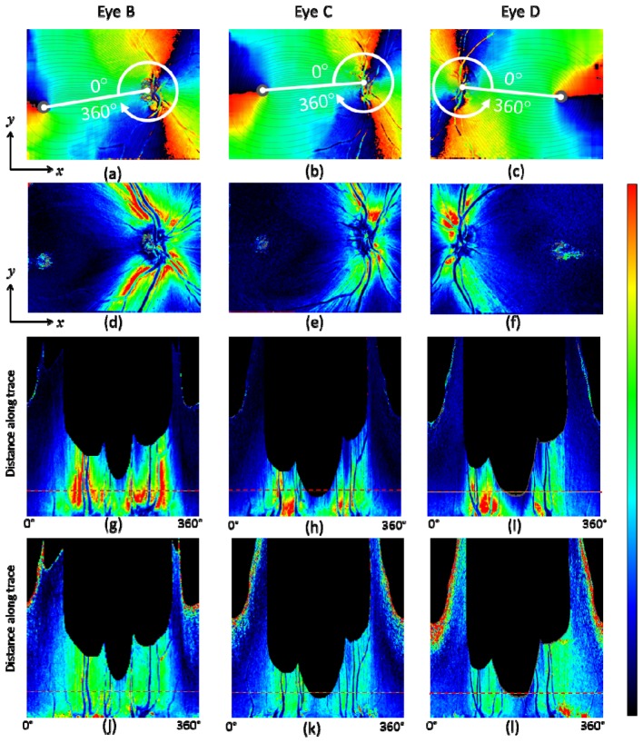
Fiber bundle tracing and retardation map along the trace for healthy eyes B, C, and D. (a) – (c): Fiber orientation en face map with traces (90 tracing lines with an azimuthal angle pitch of 4°). (d) – (f): Retardation en face maps. (g) – (i): Retardation map along trace. (j) – (l): UDR along the trace. Horizontal red dashed line in (g) – (l) indicates position at a distance of 1.7 mm from the ONH center. Healthy eye B: (a), (d), (g), (j); healthy eye C: (b), (e), (h), (k); healthy eye D: (c), (f), (i), (l). Color scales: −90° – + 90° for axis orientation, 0° – 30° for retardation, and 0° – 0.3° / μm for UDR.
Another point observed in Fig. 7(b) is a vertical asymmetry of the density of tracing lines in the area between the ONH and the fovea, i.e., less tracing lines in the inferior region than in the superior region. There is an error caused by the thin blood vessels in the area near the line connecting the fovea and the ONH (marked by magenta color rectangle in Figs. 7(a), 7(b)). The local variation range and the width of the vessel features are similar to those of nerve fiber bundles and therefore the vessels distorted the computed fiber bundle orientation. More sophisticated removal procedure for the influence of such thin vessels in the processing step is desired to eliminate this type of error. Even if such error is removed, there is another factor making the tracing lines unevenly distributed: The density of the lines indicate the 3° spacing of the RNFL bundles at the circle around the optic disc in Figs. 6 and 7. This means that where there are fewer lines there is a relatively larger area of the RGC's axons converging to the 3° sector around the optic disc [7,22]. The differences between the cases in Figs. 7(b) and 7(d) compared to Fig. 7(f) point to inter-individual differences in the distribution and course of the RNFL bundles. Exactly such differences between individuals are the justification of research efforts like ours. While Fig. 7(d) also shows an asymmetry in the vertical direction, the field of view itself is asymmetric and extends wider into the inferior region, leading to the impression of an apparent imbalance in a visual check.
For healthy eye A, a result set of en face maps and maps along the nerve fiber bundle trace are displayed in Fig. 8. In the retardation and NFL thickness en face maps (Figs. 8(b), 8(c)), bending curve patterns along the fiber bundle traces can be observed in the area around ONH and toward the foveal region. Those patterns are transformed into vertical stripe patterns in the corresponding maps along the trace (Figs. 8(e), 8(f)). Both retardation and NFL thickness decrease along the fiber bundles, from the ONH to the fovea. In the UDR maps, Figs. 8(d), 8(g), such patterns do not appear as clearly as they do in the retardation and thickness maps, and the UDR decrease along the trace toward the fovea is rather slow. Since UDR is normalized by thickness, it is basically insensitive to the fiber bundle thickness itself, but sensitive to the existence and the density of the bundles within the NFL, and of the microtubules within the ganglion cell axons. The result for these healthy eye maps indicates that the thickness of the fiber bundles decreases along the trace, while the density of the fibers in depth direction stays rather constant. The density distribution over azimuthal angles is also more uniform than that of the retardation and the thickness; stripe patterns are less visible in the UDR maps, although there is a variation, with lower UDR observed especially in the temporal area.
Figure 9 shows the results of retardation and UDR maps for three healthy eyes B, C, D. These results along with that of eye A demonstrate that our tracing method works in several eyes and that the qualitative characteristics described in the last paragraph for eye A are basically similar in other healthy eyes. In the retardation en face map Fig. 9(f), brighter color pixels spread in the region below the foveal center. This is caused by weak intensity of the OCT signal in that region, which can be observed in the OCT projection image, Fig. 7(e), especially in its right half, compared to Figs. 7(a), 7(c), and Fig. 3(c). The weak intensity is due to the sensitivity drop-off [56,57] because of a deeper positioning of the imaged retina.
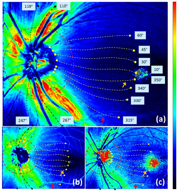
The maps along the trace can be analyzed in various ways, both qualitatively and quantitatively. In the following, we demonstrate an example of such analyses. Figure 10 illustrates one azimuthal loop (red dashed line) and 12 traced lines (yellow and black dashed lines) indicating the evaluation positions for the analysis.
Fig. 10.
Traces analyzed in Figs. 11 and 12 shown in healthy eye A, overlaid on (a) retardation, (b) thickness, (c) UDR en face maps. Red dashed line: positions at traced distance of 1.7 mm from the center of the ONH. Yellow and black dashed lines: traces corresponding to 12 azimuthal angles (values indicated near the end points of the traces); each length along the trace is 4 mm (for yellow lines) or less when the trace reached an edge (for black lines). Color scales: −90° – + 90° for axis orientation, 0° – 30° for retardation, and 0° – 0.3° / μm for UDR.
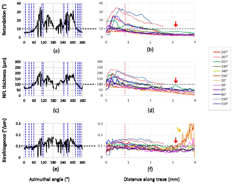
Retardation, NFL thickness, and UDR at the evaluation positions are plotted in Fig. 11 . The plots along the azimuthal loop in Figs. 11(a), 11(c), 11(e) correspond to the TSNIT (temporal-superior-nasal-inferior-temporal) graphs used for glaucoma diagnosis by SLP and OCT [18–20,44]. In this type of graph, retardation is plotted along the azimuthal angles in case of SLP measurements, whereas in case of OCT imaging NFL thickness distribution is displayed. PS-OCT provides not only NFL thickness and retardation but also UDR, which can be displayed and evaluated in a similar manner [35,48,58] and basically matches to the corresponding results in [35], Cense et al. (2004), and [48], Zotter et al. (2013) (please note that sampling points on blood vessels are not excluded in Figs. 11(a), 11(c), 11(e), which causes the somewhat jaggy appearance of the plots).
Fig. 11.
NFL retardation, thickness, and UDR characteristics in healthy eye A. (a), (b): Retardation; (c), (d): NFL thickness; (e), (f): UDR. (a), (c), (e): Circum- papillary (TSNIT) plots at a distance of 1.7 mm from ONH center; blue dashed lines indicate the 12 azimuthal angles corresponding to (b), (d), (f)). (b), (d), (f): Plots along fiber-bundle traces; red dashed line indicates the position corresponding to (a), (c), (e). Horizontal black dashed lines indicate typical values of each plots, to be used for normalization of the gradient maps in Figs. 12 and 13.
In Figs. 11(b), 11(d), 11(f), another set of plots is displayed: along-trace retardation, NFL thickness, and UDR. The traces are illustrated as yellow (in temporal zone) and black (in superior and inferior zones) dashed lines in Fig. 10. The results are in agreement with previous reports [35,46–48] (note that the comparison is made for single-path UDR and retardation). In Figs. 11(b), 11(d), 11(f), the retardation and the thickness exhibit rather monotonic decrease along the traced distance from the ONH, whereas the UDR appears rather constant, which is also in agreement with a previous report [48] (although it presented the parameters for only two thick fiber bundles along the arcade vessels, which correspond to our traces with azimuthal angles 110° and 247°).
An exceptional feature is observed in Fig. 11(f), beyond 3 mm distance, that some of the traces exhibit very steep rises; these traces are located at the center area (i.e., close to the straight line from ONH to fovea), e.g., at azimuthal angles of 10°, 30°, 350°. The steep rise is also observed in Fig. 10(c) near the foveal center (orange colored arrow). This increase in UDR is probably an artifact caused by the very low values of retardation and thickness in the corresponding area and the division operation between the small values.
Another possible artifact caused by a blood vessel can be observed in Figs. 10 and 11 (indicated by red arrows), e.g., in the tracing line with an azimuthal angle of 315° at ~3.1 mm distance from the ONH. In the NFL thickness, increase at the position of a thick vessel is distinct, while retardation has rather modest change, resulting in a noticeable drop of the UDR along the vessel.
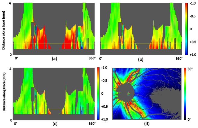
For an illustration of those parameters’ change along the fiber bundle traces, linear-fitted gradients are evaluated in the maps shown in Fig. 12 . In order to eliminate the influences of the noisy data regions discussed above, further exclusion of unreliable pixels (see gray pixels in Fig. 12(d)) was conducted before the fitting. Pixels meeting the following criteria were excluded: (i) pixels with NFL thickness less than 30 μm, (ii) pixels with Δθ > 30°, where Δθ is defined as the difference between the axis orientation obtained by polarization data from PS-OCT and the fused fiber orientation (this is to exclude the pixels with unreliable retardation, based on an assumption that error of axis orientation and error of retardation belonging to a polarization state have a positive correlation), (iii) pixels at blood vessel locations (using a segmentation by intensity thresholding), and (iv) pixels near the edges of the map; 8 pixel and 4 pixel margins at horizontal and vertical edges, respectively. In the ONH region, fitting starts at 0.75 DD from the center of the ONH (12 pixels (~0.4 mm) from the starting position of the traces (see Figs. 6 and 10)), in order to avoid the complex structures in that region and to include the positions at 1.7 mm from the center of the ONH (24 pixels (~0.8 mm) from the starting positions).
Fig. 12.
Gradient maps along the trace in healthy eye A. (a): NFL retardation gradient, (b): NFL thickness gradient, (c): NFL UDR gradient; horizontal yellow lines in the maps along the trace indicates position with distance of 1.7 mm from the ONH center; gray pixels indicate too low number of pixels for fitting. (d): Retardation en face map showing excluded pixels before the evaluation of gradient, displayed in gray color.
The gradient quantities along 5 adjacent tracing lines with an angle pitch of 1° were averaged and then fitted by linear regression as a function of distance along trace. The fitting is performed within a sliding window having a width of 30 pixels; if the window contains less than 15 pixels after exclusion of unreliable pixels, the pixel under evaluation (located at center of the window) is classified as void (shown as gray colored pixels in the gradient maps). In order to allow for a mutual comparison between the gradient quantities, which are in different physical units, normalization by 10° / mm for retardation gradient, 100 μm / mm for NFL thickness gradient, 0.1°/μm / mm for UDR gradient was conducted. The values, 10°, 100 μm, and 0.1°/μm, for the three parameters were chosen carefully to represent typical values (see horizontal black dashed lines in Fig. 11). A normalized gradient value of −1 means that the typical value decreases along the trace, reaching 0 after 1 mm distance. As can be seen from Fig. 11, in the temporal traces for example, the typical values near the starting points of the traces (black dashed lines) reach 0 after 4 mm or longer, the rates of these reductions are equivalent to a normalized gradient of −0.25 or smaller.
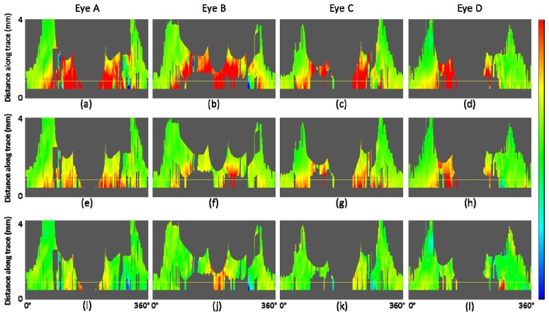
Several typical patterns can be observed in the results in Fig. 12: (i) the gradients of all three quantities exhibit negative values in most areas, (ii) retardation has relatively steep gradients (e.g., < −0.8) along superior, nasal, inferior traces, (iii) thickness has also steep gradients along superior, nasal, inferior traces (< −0.5), especially near the ONH region, (iv) in the temporal area the gradients of all three quantities are relatively flat (e.g., > −0.5), (v) UDR exhibits rather constant and relatively low and flat gradients along all the traces (e.g., > −0.5) and ~0 in most areas. In Fig. 13 , the gradient maps for all subject eyes (A, B, C, D) are shown in comparison with each other. The general patterns (i) – (v) described above can be observed in all eyes.
Fig. 13.
Gradient maps along the trace in healthy eyes A, B, C, D in comparison. (a) – (d): NFL retardation gradient, (e) – (h): NFL thickness gradient, (i) – (l): NFL UDR gradient. Horizontal yellow line indicates position at distance of 1.7 mm from the ONH center; gray pixels indicate too low number of pixels for fitting. Color scale: + 1 (blue) – −1 (red).
4. Discussion
In this study, we have demonstrated a new nerve fiber bundle tracing method and results in human retina. The method combines two technologies: PS-OCT axis orientation and NFL thickness, which have merits in ONH and foveal regions, respectively, and disadvantages vice versa. The combined use of both by fusion provides good quality images. Registration errors between the two orientation maps are avoided, since they are generated from the same PS-OCT data set recorded by a single imaging beam.
Different tissue properties were mapped along the fiber bundles: NFL retardation, thickness, UDR. Although some of the results of this work correspond to previously reported findings, only very limited results in terms of the fiber bundle tracing were presented. In [48], Zotter et al. (2013), two traces were used for a similar set of plots as demonstrated by Figs. 11(b), 11(d), 11(f) in this study. These traces were available only along the nerve fiber bundles near the thick arcade vessels which are characterized by high retardation values (~25° – 40°), and the traced positions were selected manually. In this work, the tracing is semi-automatically processed and wider regions, e.g., temporal and foveal regions with lower retardation values, are included. The tracing condition for the presented results (e.g., along-trace maps in Figs. 8, 9, 12, 13) was having 360 trace lines with an angle pitch of 1°.
Denser sampling in the azimuthal trace angles (e.g., 720, 1080 trace lines) can be employed for more detailed imaging and analysis of the fiber bundles, where e.g., the exact center of the bundles needs to be traced, in such along-trace maps. An efficient alternative is anisotropic sampling, with which the center of each individual fiber bundle is detected first by an algorithm e.g., ridge detection in the local variation maps of the retardation and the NFL thickness (near the ONH and fovea, respectively), and the dense sampling on the individual fiber bundles can be achieved based on that information, while less traces are processed at the gaps between the fiber bundles. On the other hand, in order for acquiring clearly resolved images of individual nerve fiber bundles, there are other ways: imaging by high resolution and dense sampling OCT sometimes equipped with adaptive optics followed by intensity projection of voxels within NFL [6,55]. The advantage of the method of this work is related to the blood vessels which are located at the same depth range over which the intensity projection is made. Although clear images of individual bundles can be observed in such high-resolution intensity projection images, blood vessels (especially thin vessels or capillaries) appear with similar signal levels and dimensions, which might be difficult to be excluded from the processing in terms of the bundle orientation detection and mapping. Especially, in the regions near the ONH, the effect of blood vessels cannot be neglected. This work, utilizing the polarization data which provide axis orientation directly, is less susceptible to such blood vessels. In Figs. 3(c), 3(f) and Figs. 4(d), 4(e), it can be observed that the axis orientation (Fig. 3(f)) is less affected by the blood vessels. This is because blood vessels themselves are basically polarization preserving, thereby having little influence on the polarization state from which birefringence and axis orientation are derived.
Approaching the center of the foveal region, where the retardation is as low as <10°, noise becomes a crucial factor to degrade the quality of the maps. To reduce noise, averaging was performed. The effective noise reduction by averaging enabled the generation of a continuous map from the ONH to the fovea, and it was achieved by the polarization state averaging (Appendix A) over polarization preserving voxels within B-scan and further averaging over multiple 3D volumes stabilized by retinal tracking.
The dimension of the 6 × 2 (x, y) window used for en face averaging corresponds to approximately 50 × 50 μm2. The evaluation of retardation and axis orientation within this window is based on the assumption and approximation that the birefringence of the fiber bundles is uniform within that dimension, and all variations are regarded as caused by noise. In that sense, speckle contribution within the averaging window was also treated as noise in this study; around ten speckles were averaged within one window, where the speckles are estimated to have a dimension of the optical spot size of the OCT beam (i.e. ~17 μm) [59] and the speckle patterns are different for the two orthogonal polarization states [60].
For polarization state averaging, the Stokes vector averaging with re-normalization was used. The reason is the following. Noise of birefringence related data is relatively strong in areas where the NFL is thin (foveal region) or in layers of low reflectivity like the GCL, IPL, INL. In order to reduce systematic deviations by noise (i.e, offset by Eq. (15) in Appendix B), the method with re-normalization was used.
In this work, the generation of the UDR maps is based on direct division of NFL retardation by thickness. On the other hand, it was suggested in previous publications [34,35,48] that methods using this simple division would lead to erroneous results, and instead, a linear regression method of fitting the dependence of NFL retardation to thickness data should be used. Generally, methods which average retardation values independently from corresponding axis orientation data result in a finite offset (Appendix B); this also applies to the least-squares fit used for the retardation values of A-scan pixels, especially near the position where the retardation approaches zero. The offset is large when the signal-to-noise ratio is low, which is the case for retardation values in the NFL especially around the fovea. Therefore, linear fitting would lead to systematic errors of calculated NFL UDR since the retardation offset would be propagated to UDR values. In contrast, the NFL UDR calculated in this work was based on reducing noise in retardation and NFL thickness data by elaborate averaging steps.
Another possible error factor determining the accurate retardation and UDR distributions is a dependence of birefringence and UDR on the angle between incident sampling light beam and the nerve fibers. In this study, the angle is assumed to be close to 90°, and no compensation for this angle dependence was conducted, while, in reality, if the angle decreases, the birefringence and UDR also decline. The practical range of this angle deviation from 90° can be estimated to reach up to ~10° in the cases of this study, and the corresponding error, assuming a cosine dependence, will be < 2%.
A possible application of this method could be modeling of nerve fiber bundle distribution. Efforts to build an accurate map and model of the fiber bundles have been made extensively [8,21–25]. On the other hand, there is presently no direct comparison between model and a specific in-vivo retina available (i.e., comparison to histology is not possible), which makes the evaluation of a map and model difficult and hampers efficient improvements of modeling. Comparison with tracing maps obtained by this method would be beneficial, because this method utilizes PS-OCT and polarization information, which enables a cross-check, i.e., comparison involving different physical aspects.
One of the most desirable clinical applications would be glaucoma diagnostics. Currently, commercial instruments are available that measure NFL retardation [17,61] or thickness [18–20] for this purpose. These quantities are typically measured and averaged around the ONH or within quadrants, which is rather coarse. PS-OCT provides, in addition to retardation and thickness information, a direct access to birefringence, which has been shown to decline in early experimental glaucoma before any NFL thickness changes are observable [45]. In addition, the new plot types presented in this study, plots of NFL parameters along the lengths of fiber bundles, as a function of azimuthal position of the fiber bundle around the ONH, might provide a better insight into lesions of fiber bundles, possibly enabling the early detection of bundle defects. These might be associated with localized changes of NFL parameters. Furthermore, the location of such a change along the fiber bundle trace might be correlated with the localized area of vision loss. Such changes might best be visible in the gradient maps. An interesting and important example in which this method should be tested in terms of its sensitivity is the detection of asymmetric changes regarding to MVZ [9], which will be the scope of future work.
To establish this new method for clinical applications, more measurements including statistical studies are required and a normative database is necessary for the along-trace maps, especially for the novel gradient maps. Further investigations to establish normative ranges for healthy controls and to distinguish them from pathological ranges including glaucoma patients and glaucoma suspects are planned for the future.
While tracing and analysis of NFL parameters in the papillomacular area are of interest from a modeling point of view and to demonstrate the functionality of the method, other areas might be of even greater importance for glaucoma diagnostics. For instance, early glaucomatous damage may often affect peripheral areas of the visual field, e.g., a nasal step field defect caused by nerve fiber bundle damages in the temporal side of the fovea [62–64]. The field of view of our current instrument does not allow tracing of bundles originating from temporal parts of the raphe, which corresponds to a nasal step. For this purpose, a larger scan field is required for the imaging system [65]. An alternative solution might be stitching of imaged fields recorded in different acquisition sessions. In this case, the built-in retinal tracker and the intrinsic registration between the maps for fusion can reduce the processing burden as well as the practical time required for the image acquisition sessions.
5. Conclusion
In conclusion, we have demonstrated a novel method of tracing nerve fiber bundles in human retina imaged in-vivo by PS-OCT. For three parameters, NFL retardation, thickness, and UDR, a transformation from en face maps into along-trace maps was presented. New gradient maps along trace for the three parameters indicated specific patterns illustrating the nerve fiber bundle properties. Applications including especially a nerve fiber bundle analysis for glaucoma diagnostics were discussed.
Appendix A: Method of polarization state averaging
In this appendix, we describe the method of polarization state averaging used to generate the retardation and axis orientation maps from a 3D volume dataset, and to perform multiple volume averaging including interpolation processes.
The polarization state averaging we used is based on the Stokes vector representation [66]. The Stokes vector is calculated by
| (1) |
| (2) |
| (3) |
| (4) |
where AH, AV, and are the amplitudes and the phase difference of interference signals from the two orthogonal polarization channels of SD-PS-OCT expressed by two complex numbers after Fourier transform of the spectral data (the depth dependence is neglected here for simplicity). The indices and denote horizontal and vertical linear polarization components, respectively.
Corresponding retardation and axis orientation are evaluated as [30]
| (5) |
| (6) |
By defining the ranges of retardation and axis orientation by [0°, 90°] and [-90°, + 90°], respectively, a polarization state is represented uniquely by a set of . A relationship between and can be obtained via substitutions and and double-angle formulas for Eqs. (2)–(4) with Eq. (6),
| (7) |
| (8) |
| (9) |
And inversely,
| (10) |
| (11) |
For averaging over N polarization states , where n = 1 ~ N, the vectors are averaged to obtain , where corresponds to the mean value of the respective element.
Since Eqs. (7)–(9) require that the vector is normalized, a re-normalization process is necessary before using the transformation by Eqs. (10) and (11) to obtain the corresponding retardation and axis orientation, unless the averaged vector has a norm of 1, which is in the special case when all the averaged polarization states are identical. Using the re-normalized vector , retardation and axis orientation after averaging: are derived as
| (12) |
| (13) |
This re-normalization corresponds to an extraction of the fully polarized component of the Stokes vector, in the sense that the norm of the Stokes vector recovers to 1 and the endpoint of the resulting Stokes vector is on the surface of the Poincaré sphere.
Appendix B: Possible retardation offset resulting from polarization averaging
With regard to the evaluation of averaged retardation, there is another type of methods than the Stokes vector averaging followed by re-normalization described in Appendix A. An example is to still use the Stokes vector averaging but without re-normalization, and the averaged retardation is calculated as
| (14) |
This averaged retardation is calculated only from retardation values and no contribution from axis orientation is taken into account. This type of retardation averaging methods was presented, e.g., in [67], Götzinger et al. (2011). In such a case, since the retardation is positive definite and all information that enables a counteraction of retardations is carried by axis orientation (e.g., retardations with perpendicular axis orientations counteract), an offset due to non-counteraction arises.
The offset between the retardation values in Eqs. (12) and (14) is
| (15) |
which is positive when the retardation is in the range of [0°, 45°], and negative when it is within [45°, 90°]. For example, in the case that the true value of the retardation is 0° and is detected with random noise which distributes the Stokes vectors of individual measurements uniformly and symmetrically within a certain region on the surface of the Poincaré sphere, should converge to zero after the polarization state averaging for noise removal, while this offset gives rise to a non-zero retardation value for even after averaging. The wider the spread on the surface of the Poincaré sphere by noise is, the larger the absolute value of the offset becomes. Mathematically, the re-normalization procedure takes the axis orientation information, carried by and , into account, which leads to a reduction of the offset.
References and links
- 1.Pollock S. C., Miller N. R., “The Retinal Nerve Fiber Layer,” Int. Ophthalmol. Clin. 26(4), 201–221 (1986). 10.1097/00004397-198602640-00019 [DOI] [PubMed] [Google Scholar]
- 2.Ogden T. E., “Nerve fiber layer of the primate retina: morphometric analysis,” Invest. Ophthalmol. Vis. Sci. 25(1), 19–29 (1984). [PubMed] [Google Scholar]
- 3.Huang X. R., “Polarization properties of the retinal nerve fiber layer,” Bull. Soc. Belge Ophtalmol. 302, 71–88 (2006). [PubMed] [Google Scholar]
- 4.Quigley H. A., Addicks E. M., Green W. R., “Optic nerve damage in human glaucoma. III. Quantitative correlation of nerve fiber loss and visual field defect in glaucoma, ischemic neuropathy, papilledema, and toxic neuropathy,” Arch. Ophthalmol. 100(1), 135–146 (1982). 10.1001/archopht.1982.01030030137016 [DOI] [PubMed] [Google Scholar]
- 5.Jonas J. B., Müller-Bergh J. A., Schlötzer-Schrehardt U. M., Naumann G. O., “Histomorphometry of the human optic nerve,” Invest. Ophthalmol. Vis. Sci. 31(4), 736–744 (1990). [PubMed] [Google Scholar]
- 6.Kocaoglu O. P., Cense B., Jonnal R. S., Wang Q., Lee S., Gao W., Miller D. T., “Imaging retinal nerve fiber bundles using optical coherence tomography with adaptive optics,” Vision Res. 51(16), 1835–1844 (2011). 10.1016/j.visres.2011.06.013 [DOI] [PMC free article] [PubMed] [Google Scholar]
- 7.Hood D. C., Kardon R. H., “A framework for comparing structural and functional measures of glaucomatous damage,” Prog. Retin. Eye Res. 26(6), 688–710 (2007). 10.1016/j.preteyeres.2007.08.001 [DOI] [PMC free article] [PubMed] [Google Scholar]
- 8.Jansonius N. M., Nevalainen J., Selig B., Zangwill L. M., Sample P. A., Budde W. M., Jonas J. B., Lagrèze W. A., Airaksinen P. J., Vonthein R., Levin L. A., Paetzold J., Schiefer U., “A mathematical description of nerve fiber bundle trajectories and their variability in the human retina,” Vision Res. 49(17), 2157–2163 (2009). 10.1016/j.visres.2009.04.029 [DOI] [PMC free article] [PubMed] [Google Scholar]
- 9.Hood D. C., Raza A. S., de Moraes C. G. V., Liebmann J. M., Ritch R., “Glaucomatous damage of the macula,” Prog. Retin. Eye Res. 32, 1–21 (2013). 10.1016/j.preteyeres.2012.08.003 [DOI] [PMC free article] [PubMed] [Google Scholar]
- 10.Varma R., Skaf M., Barron E., “Retinal nerve fiber layer thickness in normal human eyes,” Ophthalmology 103(12), 2114–2119 (1996). 10.1016/S0161-6420(96)30381-3 [DOI] [PubMed] [Google Scholar]
- 11.Quigley H. A., Broman A. T., “The number of people with glaucoma worldwide in 2010 and 2020,” Br. J. Ophthalmol. 90(3), 262–267 (2006). 10.1136/bjo.2005.081224 [DOI] [PMC free article] [PubMed] [Google Scholar]
- 12.Diekmann H., Fischer D., “Glaucoma and optic nerve repair,” Cell Tissue Res. 353(2), 327–337 (2013). 10.1007/s00441-013-1596-8 [DOI] [PubMed] [Google Scholar]
- 13.Harwerth R. S., Wheat J. L., Fredette M. J., Anderson D. R., “Linking structure and function in glaucoma,” Prog. Retin. Eye Res. 29(4), 249–271 (2010). 10.1016/j.preteyeres.2010.02.001 [DOI] [PMC free article] [PubMed] [Google Scholar]
- 14.Anton A., Yamagishi N., Zangwill L., Sample P. A., Weinreb R. N., “Mapping structural to functional damage in glaucoma with standard automated perimetry and confocal scanning laser ophthalmoscopy,” Am. J. Ophthalmol. 125(4), 436–446 (1998). 10.1016/S0002-9394(99)80183-4 [DOI] [PubMed] [Google Scholar]
- 15.Garway-Heath D. F., Poinoosawmy D., Fitzke F. W., Hitchings R. A., “Mapping the visual field to the optic disc in normal tension glaucoma eyes,” Ophthalmology 107(10), 1809–1815 (2000). 10.1016/S0161-6420(00)00284-0 [DOI] [PubMed] [Google Scholar]
- 16.McKendrick A. M., “Recent developments in perimetry: test stimuli and procedures,” Clin. Exp. Optom. 88(2), 73–80 (2005). 10.1111/j.1444-0938.2005.tb06671.x [DOI] [PubMed] [Google Scholar]
- 17.Garway-Heath D., “Optic disc imaging,” Focus - Issue 22 Summer 2002, by R. Coll. Ophthalmol. London (2002). [Google Scholar]
- 18.Schuman J. S., Hee M. R., Puliafito C. A., Wong C., Pedut-Kloizman T., Lin C. P., Hertzmark E., Izatt J. A., Swanson E. A., Fujimoto J. G., “Quantification of Nerve Fiber Layer Thickness in Normal and Glaucomatous Eyes Using Optical Coherence Tomography,” Arch. Ophthalmol. 113(5), 586–596 (1995). 10.1001/archopht.1995.01100050054031 [DOI] [PubMed] [Google Scholar]
- 19.Blumenthal E. Z., Williams J. M., Weinreb R. N., Girkin C. A., Berry C. C., Zangwill L. M., “Reproducibility of nerve fiber layer thickness measurements by use of optical coherence tomography,” Ophthalmology 107(12), 2278–2282 (2000). 10.1016/S0161-6420(00)00341-9 [DOI] [PubMed] [Google Scholar]
- 20.Paunescu L. A., Schuman J. S., Price L. L., Stark P. C., Beaton S., Ishikawa H., Wollstein G., Fujimoto J. G., “Reproducibility of nerve fiber thickness, macular thickness, and optic nerve head measurements using stratus OCT,” Invest. Ophthalmol. Vis. Sci. 45(6), 1716–1724 (2004). 10.1167/iovs.03-0514 [DOI] [PMC free article] [PubMed] [Google Scholar]
- 21.Denniss J., Turpin A., Tanabe F., Matsumoto C., McKendrick A. M., “Structure-function mapping: variability and conviction in tracing retinal nerve fiber bundles and comparison to a computational model,” Invest. Ophthalmol. Vis. Sci. 55(2), 728–736 (2014). 10.1167/iovs.13-13142 [DOI] [PubMed] [Google Scholar]
- 22.Lamparter J., Russell R. A., Zhu H., Asaoka R., Yamashita T., Ho T., Garway-Heath D. F., “The influence of intersubject variability in ocular anatomical variables on the mapping of retinal locations to the retinal nerve fiber layer and optic nerve head,” Invest. Ophthalmol. Vis. Sci. 54(9), 6074–6082 (2013). 10.1167/iovs.13-11902 [DOI] [PubMed] [Google Scholar]
- 23.Airaksinen P. J., Doro S., Veijola J., “Conformal geometry of the retinal nerve fiber layer,” Proc. Natl. Acad. Sci. U.S.A. 105(50), 19690–19695 (2008). 10.1073/pnas.0801621105 [DOI] [PMC free article] [PubMed] [Google Scholar]
- 24.Nevalainen J., “Utilisation of the structure of the retinal nerve fiber layer and test strategy in visual field examination,” Acta Universitatis Ouluensis. D 1057, 1057 (2010). [Google Scholar]
- 25.Erler N. S., Bryan S. R., Eilers P. H. C., Lesaffre E. M. E. H., Lemij H. G., Vermeer K. A., “Optimizing structure-function relationship by maximizing correspondence between glaucomatous visual fields and mathematical retinal nerve fiber models,” Invest. Ophthalmol. Vis. Sci. 55(4), 2350–2357 (2014). 10.1167/iovs.13-12492 [DOI] [PubMed] [Google Scholar]
- 26.Carreras F. J., Medina J., Ruiz-Lozano M., Carreras I., Castro J. L., “Virtual tissue engineering and optic pathways: plotting the course of the axons in the retinal nerve fiber layer,” Invest. Ophthalmol. Vis. Sci. 55(5), 3107–3119 (2014). 10.1167/iovs.13-13387 [DOI] [PubMed] [Google Scholar]
- 27.Hee M. R., Huang D., Swanson E. A., Fujimoto J. G., “Polarization-sensitive low-coherence reflectometer for birefringence characterization and ranging,” J. Opt. Soc. Am. B 9(6), 903 (1992). 10.1364/JOSAB.9.000903 [DOI] [Google Scholar]
- 28.de Boer J. F., Milner T. E., van Gemert M. J., Nelson J. S., “Two-dimensional birefringence imaging in biological tissue by polarization-sensitive optical coherence tomography,” Opt. Lett. 22(12), 934–936 (1997). 10.1364/OL.22.000934 [DOI] [PubMed] [Google Scholar]
- 29.de Boer J. F., Milner T. E., Nelson J. S., “Determination of the depth-resolved Stokes parameters of light backscattered from turbid media by use of polarization-sensitive optical coherence tomography,” Opt. Lett. 24(5), 300–302 (1999). 10.1364/OL.24.000300 [DOI] [PubMed] [Google Scholar]
- 30.Hitzenberger C. K., Goetzinger E., Sticker M., Pircher M., Fercher A. F., “Measurement and imaging of birefringence and optic axis orientation by phase resolved polarization sensitive optical coherence tomography,” Opt. Express 9(13), 780–790 (2001). 10.1364/OE.9.000780 [DOI] [PubMed] [Google Scholar]
- 31.de Boer J. F., Milner T. E., “Review of polarization sensitive optical coherence tomography and Stokes vector determination,” J. Biomed. Opt. 7(3), 359–371 (2002). 10.1117/1.1483879 [DOI] [PubMed] [Google Scholar]
- 32.Yasuno Y., Makita S., Sutoh Y., Itoh M., Yatagai T., “Birefringence imaging of human skin by polarization-sensitive spectral interferometric optical coherence tomography,” Opt. Lett. 27(20), 1803–1805 (2002). 10.1364/OL.27.001803 [DOI] [PubMed] [Google Scholar]
- 33.Stifter D., Burgholzer P., Hoeglinger O., Götzinger E., Hitzenberger C. K., “Polarisation-sensitive optical coherence tomography for material characterisation and strain-field mapping,” Appl. Phys., A Mater. Sci. Process. 76, 947–951 (2003). 10.1007/s00339-002-2065-5 [DOI] [Google Scholar]
- 34.Cense B., Chen T. C., Park B. H., Pierce M. C., De Boer J. F., “In vivo depth-resolved birefringence measurements of the human retinal nerve fiber layer by polarization-sensitive optical coherence tomography,” Opt. Lett. 27, 1610–1612 (2002). [DOI] [PubMed] [Google Scholar]
- 35.Cense B., Chen T. C., Park B. H., Pierce M. C., de Boer J. F., “Thickness and birefringence of healthy retinal nerve fiber layer tissue measured with polarization-sensitive optical coherence tomography,” Invest. Ophthalmol. Vis. Sci. 45(8), 2606–2612 (2004). 10.1167/iovs.03-1160 [DOI] [PubMed] [Google Scholar]
- 36.Pircher M., Götzinger E., Leitgeb R., Sattmann H., Findl O., Hitzenberger C. K., “Imaging of polarization properties of human retina in vivo with phase resolved transversal PS-OCT,” Opt. Express 12(24), 5940–5951 (2004). 10.1364/OPEX.12.005940 [DOI] [PubMed] [Google Scholar]
- 37.Yamanari M., Makita S., Yasuno Y., “Polarization-sensitive swept-source optical coherence tomography with continuous source polarization modulation,” Opt. Express 16(8), 5892–5906 (2008). 10.1364/OE.16.005892 [DOI] [PubMed] [Google Scholar]
- 38.Götzinger E., Pircher M., Geitzenauer W., Ahlers C., Baumann B., Michels S., Schmidt-Erfurth U., Hitzenberger C. K., “Retinal pigment epithelium segmentation by polarization sensitive optical coherence tomography,” Opt. Express 16(21), 16410–16422 (2008). 10.1364/OE.16.016410 [DOI] [PMC free article] [PubMed] [Google Scholar]
- 39.Baumann B., Gotzinger E., Pircher M., Sattmann H., Schuutze C., Schlanitz F., Ahlers C., Schmidt-Erfurth U., Hitzenberger C. K., “Segmentation and quantification of retinal lesions in age-related macular degeneration using polarization-sensitive optical coherence tomography,” J. Biomed. Opt. 15(6), 061704 (2010). 10.1117/1.3499420 [DOI] [PMC free article] [PubMed] [Google Scholar]
- 40.Baumann B., Baumann S. O., Konegger T., Pircher M., Götzinger E., Schlanitz F., Schütze C., Sattmann H., Litschauer M., Schmidt-Erfurth U., Hitzenberger C. K., “Polarization sensitive optical coherence tomography of melanin provides intrinsic contrast based on depolarization,” Biomed. Opt. Express 3(7), 1670–1683 (2012). 10.1364/BOE.3.001670 [DOI] [PMC free article] [PubMed] [Google Scholar]
- 41.Cense B., Wang Q., Lee S., Zhao L., Elsner A. E., Hitzenberger C. K., Miller D. T., “Henle fiber layer phase retardation measured with polarization-sensitive optical coherence tomography,” Biomed. Opt. Express 4(11), 2296–2306 (2013). 10.1364/BOE.4.002296 [DOI] [PMC free article] [PubMed] [Google Scholar]
- 42.Pircher M., Hitzenberger C. K., Schmidt-Erfurth U., “Polarization sensitive optical coherence tomography in the human eye,” Prog. Retin. Eye Res. 30(6), 431–451 (2011). 10.1016/j.preteyeres.2011.06.003 [DOI] [PMC free article] [PubMed] [Google Scholar]
- 43.Huang X.-R., Knighton R. W., Cavuoto L. N., “Microtubule contribution to the reflectance of the retinal nerve fiber layer,” Invest. Ophthalmol. Vis. Sci. 47(12), 5363–5367 (2006). 10.1167/iovs.06-0451 [DOI] [PubMed] [Google Scholar]
- 44.Dreher A. W., Reiter K., Weinreb R. N., “Spatially resolved birefringence of the retinal nerve fiber layer assessed with a retinal laser ellipsometer,” Appl. Opt. 31(19), 3730–3735 (1992). 10.1364/AO.31.003730 [DOI] [PubMed] [Google Scholar]
- 45.Fortune B., Burgoyne C. F., Cull G., Reynaud J., Wang L., “Onset and progression of peripapillary retinal nerve fiber layer (RNFL) retardance changes occur earlier than RNFL thickness changes in experimental glaucoma,” Invest. Ophthalmol. Vis. Sci. 54(8), 5653–5661 (2013). 10.1167/iovs.13-12219 [DOI] [PMC free article] [PubMed] [Google Scholar]
- 46.Götzinger E., Pircher M., Baumann B., Hirn C., Vass C., Hitzenberger C. K., “Retinal nerve fiber layer birefringence evaluated with polarization sensitive spectral domain OCT and scanning laser polarimetry: a comparison,” J. Biophotonics 1(2), 129–139 (2008). 10.1002/jbio.200710009 [DOI] [PubMed] [Google Scholar]
- 47.Yamanari M., Miura M., Makita S., Yatagai T., Yasuno Y., “Phase retardation measurement of retinal nerve fiber layer by polarization-sensitive spectral-domain optical coherence tomography and scanning laser polarimetry,” J. Biomed. Opt. 13(1), 014013 (2008). 10.1117/1.2841024 [DOI] [PubMed] [Google Scholar]
- 48.Zotter S., Pircher M., Götzinger E., Torzicky T., Yoshida H., Hirose F., Holzer S., Kroisamer J., Vass C., Schmidt-Erfurth U., Hitzenberger C. K., “Measuring retinal nerve fiber layer birefringence, retardation, and thickness using wide-field, high-speed polarization sensitive spectral domain OCT,” Invest. Ophthalmol. Vis. Sci. 54(1), 72–84 (2013). 10.1167/iovs.12-10089 [DOI] [PubMed] [Google Scholar]
- 49.Sugita M., Zotter S., Pircher M., Makihira T., Saito K., Tomatsu N., Sato M., Roberts P., Schmidt-Erfurth U., Hitzenberger C. K., “Motion artifact and speckle noise reduction in polarization sensitive optical coherence tomography by retinal tracking,” Biomed. Opt. Express 5(1), 106–122 (2014). 10.1364/BOE.5.000106 [DOI] [PMC free article] [PubMed] [Google Scholar]
- 50.Götzinger E., Baumann B., Pircher M., Hitzenberger C. K., “Polarization maintaining fiber based ultra-high resolution spectral domain polarization sensitive optical coherence tomography,” Opt. Express 17(25), 22704–22717 (2009). 10.1364/OE.17.022704 [DOI] [PMC free article] [PubMed] [Google Scholar]
- 51.“Safety of laser products - Part 1: Equipment classification and requirements,” IEC 60825–1 (2007).
- 52.Pircher M., Götzinger E., Baumann B., Hitzenberger C. K., “Corneal birefringence compensation for polarization sensitive optical coherence tomography of the human retina,” J. Biomed. Opt. 12(4), 041210 (2007). 10.1117/1.2771560 [DOI] [PubMed] [Google Scholar]
- 53.Babatunde I. G., “Fingerprint Image Enhancement : Segmentation to Thinning,” Int. J. Adv. Comput. Sci. Appl. 3, 15–24 (2012). [Google Scholar]
- 54.Hong L., Wan Y., Jain A., “Fingerprint image enhancement : algorithm and performance evaluation,” IEEE Trans. Pattern Anal. Mach. Intell. 20(8), 777–789 (1998). 10.1109/34.709565 [DOI] [Google Scholar]
- 55.Chauhan B. C., Sharpe G. P., Hutchison D. M., “Imaging of the temporal raphe with optical coherence tomography,” Ophthalmology 121(11), 2287–2288 (2014). 10.1016/j.ophtha.2014.06.023 [DOI] [PubMed] [Google Scholar]
- 56.Leitgeb R., Hitzenberger C. K., Fercher A. F., “Performance of fourier domain vs. time domain optical coherence tomography,” Opt. Express 11(8), 889–894 (2003). 10.1364/OE.11.000889 [DOI] [PubMed] [Google Scholar]
- 57.Bajraszewski T., Wojtkowski M., Szkulmowski M., Szkulmowska A., Huber R., Kowalczyk A., “Improved spectral optical coherence tomography using optical frequency comb,” Opt. Express 16(6), 4163–4176 (2008). 10.1364/OE.16.004163 [DOI] [PubMed] [Google Scholar]
- 58.Elmaanaoui B., Wang B., Dwelle J. C., McElroy A. B., Liu S. S., Rylander H. G., Milner T. E., “Birefringence measurement of the retinal nerve fiber layer by swept source polarization sensitive optical coherence tomography,” Opt. Express 19(11), 10252–10268 (2011). [DOI] [PMC free article] [PubMed] [Google Scholar]
- 59.Schmitt J. M., Xiang S. H., Yung K. M., “Speckle in optical coherence tomography,” J. Biomed. Opt. 4(1), 95–105 (1999). 10.1117/1.429925 [DOI] [PubMed] [Google Scholar]
- 60.Ren H., Ding Z., Zhao Y., Miao J., Nelson J. S., Chen Z., “Phase-resolved functional optical coherence tomography: simultaneous imaging of in situ tissue structure, blood flow velocity, standard deviation, birefringence, and Stokes vectors in human skin,” Opt. Lett. 27(19), 1702–1704 (2002). 10.1364/OL.27.001702 [DOI] [PubMed] [Google Scholar]
- 61.Colen T. P., Tjon-Fo-sang M. J., Mulder P. G., Lemij H. G., “Reproducibility of measurements with the nerve fiber analyzer (NfA/GDx),” J. Glaucoma 9(5), 363–370 (2000). 10.1097/00061198-200010000-00004 [DOI] [PubMed] [Google Scholar]
- 62.Lau L.-I., Liu C. J., Chou J. C.-K., Hsu W.-M., Liu J.-H., “Patterns of visual field defects in chronic angle-closure glaucoma with different disease severity,” Ophthalmology 110(10), 1890–1894 (2003). 10.1016/S0161-6420(03)00666-3 [DOI] [PubMed] [Google Scholar]
- 63.Werner E. B., Drance S. M., “Early Visual Field Disturbances in Glaucoma,” Arch. Ophthalmol. 95(7), 1173–1175 (1977). 10.1001/archopht.1977.04450070071002 [DOI] [PubMed] [Google Scholar]
- 64.J. R. Piltz-seymour, O. Heath-phillip, and M. Stephen, “Chapter 49 Visual Fields in Glaucoma,” in Duane’s Ophthalmology on CD-ROM, W. Tasman and E. A. Jaeger, eds. (Lippincott Williams & Wilkins Publishers, 2006), Vol. 3. [Google Scholar]
- 65.Zotter S., Pircher M., Torzicky T., Baumann B., Yoshida H., Hirose F., Roberts P., Ritter M., Schütze C., Götzinger E., Trasischker W., Vass C., Schmidt-Erfurth U., Hitzenberger C. K., “Large-field high-speed polarization sensitive spectral domain OCT and its applications in ophthalmology,” Biomed. Opt. Express 3(11), 2720–2732 (2012). [DOI] [PMC free article] [PubMed] [Google Scholar]
- 66.Malykin G. B., “Use of the poincare sphere in polarization optics and classical and quantum mechanics. review,” Radiophys. Quantum Electron. 40(3), 175–195 (1997). 10.1007/BF02676342 [DOI] [Google Scholar]
- 67.Götzinger E., Pircher M., Baumann B., Schmoll T., Sattmann H., Leitgeb R. A., Hitzenberger C. K., “Speckle noise reduction in high speed polarization sensitive spectral domain optical coherence tomography,” Opt. Express 19(15), 14568–14585 (2011). 10.1364/OE.19.014568 [DOI] [PMC free article] [PubMed] [Google Scholar]


