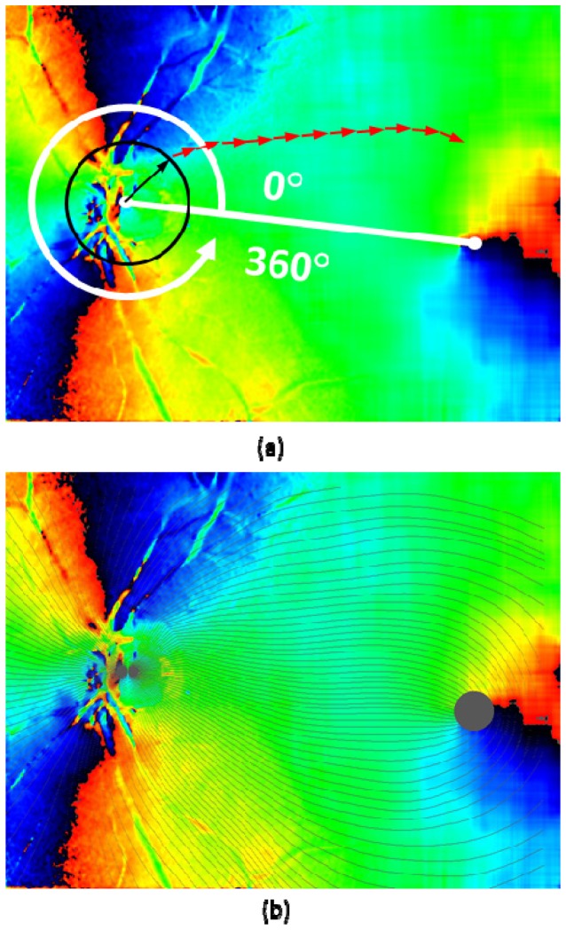
Fig. 6.
Fiber bundle tracing by fiber orientation map. (a): Tracing process; black and red arrows overlaid on the fiber orientation map indicate the tracing steps (arrows are not in scale; length of black arrow: 0.5 DD, red arrow: 0.035 mm). (b): Traced lines (displayed in black color) with azimuthal angle of 3° pitch (120 lines) overlaid on axis orientation map.

