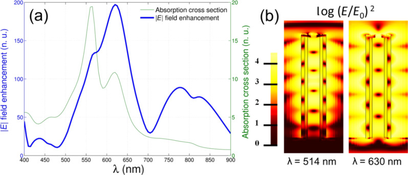
Figure 3.
(a) Finite element method simulations of a silver nanotube with 1.4 µm height, 160 nm width, surface roughness of 4 nm and illuminated by TM polarized light impinging at 5°. The blue line represents the electric field enhancement calculated 1 nm above the upper antenna edge and normalized with respect to the impinging wave amplitude. The green line is the metal absorption cross section normalized to the incident power impinging on the antenna geometrical cross section. (b) Electric field maps corresponding to an excitation wavelength of 514 nm and 630 nm.

