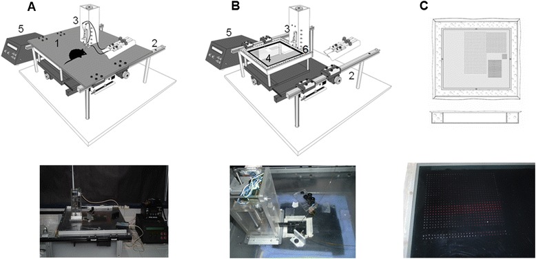
Figure 1.

The device developed for sampling and reading of the glutamate concentration in dialysates. Top of A and B show the schematic device with all of its components: 1, the cover; 2, the stage movable in two axes; 3, the Z axis with the needle for sampling; 4, polycarbonate plate; 5, the control box used to program the device in terms of the number of rows and the frequency of the sampling process, as well as for reading; and 6, space for a wet sponge to create the humidity chamber when the cover slides over it. Actual images of the schematic device are shown at the bottom. C, Schematic and actual images (top and bottom, respectively) of fluorescence samples obtained at the end of an experiment.
